Supercharge Your Innovation With Domain-Expert AI Agents!

Filter press end assembly and fluid management system for use in unipolar electrochemical devices

a filter press and end assembly technology, applied in the direction of electrolysis components, electrolysis processes, cells, etc., can solve the problems of unipolar and monopolar cells, lower efficiency, and higher electronic resistance voltage loss, so as to improve the rigidity of the end clamp

Active Publication Date: 2022-03-10
KEY DH INC IP STRATEGIQUES DH INC
View PDF0 Cites 0 Cited by
  • Summary
  • Abstract
  • Description
  • Claims
  • Application Information

AI Technical Summary

Benefits of technology

The patent text describes a design for a rigid hollow frame that includes lateral struts to reinforce its rigidity. Additionally, the end clamp may also have reinforcing gussets to further improve its rigidity. These features make the frame and clamp stronger and more durable.

Problems solved by technology

This has traditionally led to higher voltage losses due to higher electronic resistance voltage loss, and thus lower efficiency, for unipolar and monopolar cells as compared to bipolar cells for similar current densities and similar electroactive structures.
Historically, the contribution of electronic resistance to cell voltage losses in traditional unipolar and monopolar designs presented the greatest barrier to the continued commercialization of these technologies.
However, the utilization of higher current densities does not in itself lead to improved efficiency or improved plant economics.
This leads to rapid depolarization upon removal of the forward current, bypass currents during normal operation, and exposure to high potential differences leading to a need for choice of materials able to withstand this environment.
However, because of the high part count, complex assemblies, resistance within the conductive pathways of a single cell, and difficulties inherent in changing the surface area per cell, “tank type” unipolar water electrolysers, such configurations were generally replaced by comparatively more efficient “filter press type” configurations over time.
However, these “tank type” designs eliminated need for mixing electrolyte between cells and the related by-pass currents and very high potential differences across multicell arrays.
However, while the monopolar double plate design of U.S. Pat. No. 6,080,290 overcame the cited prior limitations of the unipolar tank type cell, the electrolyser of U.S. Pat. No. 6,080,290 was limited by the design of its “end assemblies and fluid management system” in other words, the components positioned on opposing ends of the filter press wherein the stack is physically terminated, allowing for the filter press to be clamped and interact with outside systems.
The sharing of electrolyte between adjacent monopolar filter press cell stacks presents great risks of end box material instability when applied to alkaline water electrolysis.
However, during start up and shut down, the presence of reverse currents within the shared electrolyte pool spanning multiple electrochemical cells would induce corrosion of even the cathodic end boxes, should they be provided from a preferred inexpensive material such as carbon steel.
Further, the end boxes of U.S. Pat. No. 6,080,290 are not optimally designed such that they can be readily and cheaply nickel plated, as they comprise crevices and complex geometries being of one integral tube, making them altogether expensive to protect from corrosion, and limiting the use of cheap materials in cathode regions which may otherwise be employed in alkaline water electrolysis processes.
The economics of the design of U.S. Pat. No. 6,080,290 are therefore rendered undesirably expensive in view of its end box and fluid management system design.
Further, the endboxes were not themselves an integral part of the monopolar filter press, being positioned external to each electrochemical cell stack, thus consuming excess spatial footprint beyond the dimensions of the core filter press.
With this construction, there are additional limitations imposed for the desired use case of large-scale alkaline water electrolysis.
As one example, there are limitations imposed by the mixing of electrolytes between electrochemical cells within the same filter press stack.
The electrolyte is exposed to the summation of all voltages across each individual cell within the filter press, increasing the likelihood of corrosion currents on inexpensive materials such as carbon steel.
The necessity of applying expensive materials to cathode components due to corrosion currents inherent from the bipolar configuration increases the cost of scaling the system.
Additionally, there are practical limits on the surface area of a single bipolar cell.
Practical surface area limits are imposed as the electrolytic reactants and products need to distribute throughout the bipolar electrode structure, while balancing limits in practical manufacturing techniques as well as transportation of a filter press from its point of fabrication to the operating site.
Furthermore, multiple bipolar filter presses are not practically employed in parallel with each other to increase this amperage, due to the differences in resistivity between each filter press.
Therefore, for the purpose of creating large surface area electrolysis cells, bipolar cells are not practical.
Without a practical method to increase total current flowing through each electrochemical cell, the use of highly cost competitive and efficient high current rectifiers cannot be realized.
Finally, the bipolar electrolyser module of Stemp in U.S. Pat. No. 8,308,917 is optimized for a bipolar filter press of a substantially circular configuration, and could not be functionally applied to a unipolar or monopolar filter press in a substantially rectangular configuration.
This results in a more intensive design.
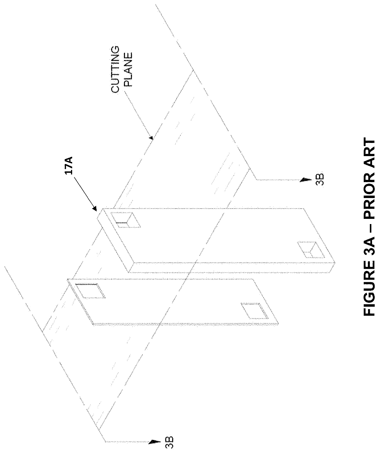
However, this cavity is difficult to fabricate due to its placement within the design.
The unitary construction of the end piece makes nickel platting difficult, due to the shape and the internal chambers.
Furthermore, the unitary construction makes it difficult to add mechanical support members, and internal tubing, and also increases the difficulty in maintenance.
In addition, the unitary construction of this end assembly does not allow for separate sealing flanges, and has limitations to size and shapes.
By the year 2020, the cost of implementing renewable forms of electricity production through technologies such as wind turbines and photovoltaics has dramatically fallen from historical levels.

Method used


Image

  • Filter press end assembly and fluid management system for use in unipolar electrochemical devices
  • Filter press end assembly and fluid management system for use in unipolar electrochemical devices
  • Filter press end assembly and fluid management system for use in unipolar electrochemical devices

Examples


Embodiment Construction

[0112]Various embodiments and aspects of the disclosure will be described with reference to details discussed below. The following description and drawings are illustrative of the disclosure and are not to be construed as limiting the disclosure. The figures are not to scale. The dimensions of the apertures in the figures are non-limiting and can be adjusted by the designer for flow and pressure management. Numerous specific details are described to provide a thorough understanding of various embodiments of the present disclosure. However, in certain instances, well-known or conventional details are not described to provide a concise discussion of embodiments of the present disclosure. As used herein, the terms, “comprises” and “comprising” are to be construed as being inclusive and open ended, and not exclusive. Specifically, when used in the specification and claims, the terms “comprise” and “comprising” and variations thereof mean the specified features, steps or components are i...


PUM

PropertyMeasurementUnit
currentaaaaaaaaaa
currentaaaaaaaaaa
thicknessaaaaaaaaaa

Abstract

Disclosed is an end assembly for use in a unipolar filter press electrolyser, where the unipolar filter press electrolyser has a filter press stack. The end assembly of the unipolar filter press electrolyser includes an end plate component having two apertures, the two apertures being alignable with channels formed in the filter press stack. The two apertures include a first aperture configured to receive a stream of liquid electrolyte and gases from the filter press stack, and a second aperture configured to receive a stream of recirculated liquid electrolyte. In addition, the end assembly includes an end clamp configured to apply a clamping force on the end plate component to securely retain the filter press stack. The end clamp includes one gas offtake port to extract gases from the stream of liquid electrolyte and gases from the first aperture and discharge the gases out of the unipolar filter press electrolyser.

Description

CROSS-REFERENCE TO RELATED APPLICATIONS[0001]This application claims priority to U.S. Provisional Application Ser. No. 63 / 076,180, filed on Sep. 9, 2020, and which is incorporated by reference.FIELD OF THE INVENTION[0002]This disclosure relates to novel structures for use in electrochemical devices such as electrolysers, consisting in a filter press end assembly, suitable for use in unipolar or monopolar electrolysis of an alkali aqueous solution of water which can be configured in one or more filter press arrangements.BACKGROUND OF THE INVENTION[0003]Electrochemical cell technology is designed such that an applied electric current induces reactions within a cell, converting available reactants into desired products. An electrolytic cell, or electrolysis cell, is one preferred method of accomplishing this conversion. Electrolysis cells require the conduction of electricity, typically direct current, from an external source to a polarized electrode. They further require conduction aw...

Claims


Application Information

Patent Timeline
Patent Type & Authority Applications(United States)
IPC IPC(8): C25B9/73C25B9/60C25B1/04C25B15/08
CPCC25B9/73C25B9/60C25B1/34C25B15/08C25B1/04C25B9/05C25B15/00C25B9/63C25B9/67
Inventor STUART, ANDREW T. B.LACHANCE, RAYNALD G.STUART, EDWARD D. B.SPAL, JAIDEEP S.
Owner KEY DH INC IP STRATEGIQUES DH INC
Features
  • R&D
  • Intellectual Property
  • Life Sciences
  • Materials
  • Tech Scout
  • Unparalleled Data Quality
  • Higher Quality Content
  • 60% Fewer Hallucinations
Learn More