
System and method for treating exhaust fluid from semiconductor manufacturing equipment

a technology of exhaust fluid and semiconductor manufacturing equipment, which is applied in the direction of positive displacement liquid engine, liquid fuel engine, separation process, etc., can solve the problems of shortening the lifespan of the vacuum pump, corroding metal surfaces, and deteriorating the performance of the vacuum pump

Pending Publication Date: 2022-03-31
PLAN
View PDF0 Cites 0 Cited by
  • Summary
  • Abstract
  • Description
  • Claims
  • Application Information

AI Technical Summary

Benefits of technology

The present invention provides a system and method for treating exhaust fluid from semiconductor manufacturing equipment. The invention solves issues with previous methods by using a booster pump and a dry pump to effectively remove process byproducts. The invention also increases the retention time of the cleaning gases in the pump by adjusting the pressure in the pump. The main technical effects of the invention are improved removal efficiency of process byproducts and increased reaction time of the cleaning gases with the process byproducts.

Problems solved by technology

Among the process byproducts, such as unreacted gas, waste gas, etc., HF, fluorides, chlorides, etc. move through the vacuum pump and the insides of pipes and thus cause corrosion of metal surfaces, and most of gases used in the manufacturing processes are environmental pollutants and must thus be removed before they are finally discharged into the atmosphere.
Further, while fine particles and metals generated during the manufacturing processes pass through parts installed in various transfer paths in which fluid is transferred, such as pipes, the fine particles and metals transition to a powder form (for example, SiO2 powder) via a phase transition process due to cooling or a change in pressure, and such powder may shorten the lifespan of the vacuum pump.
Here, the process byproducts are cooled and thus grown in a powder form while passing through pipes configured to connect the process chamber and the vacuum pump, and are accumulated on a rotor in the vacuum pump as time passes by, and such accumulation of the powder deteriorates the performance of the vacuum pump and shortens the lifespan of the vacuum pump.

Method used


Image

  • System and method for treating exhaust fluid from semiconductor manufacturing equipment
  • System and method for treating exhaust fluid from semiconductor manufacturing equipment
  • System and method for treating exhaust fluid from semiconductor manufacturing equipment

Examples


Embodiment Construction

[0050]Hereinafter reference will now be made in detail to various embodiments of the present invention, examples of which are illustrated in the accompanying drawings and described below. While the invention will be described in conjunction with exemplary embodiments, it will be understood that the present description is not intended to limit the invention to the exemplary embodiments. On the contrary, the invention is intended to cover not only the exemplary embodiments, but also various alternatives, modifications, equivalents and other embodiments, which may be included within the spirit and scope of the invention as defined by the appended claims.

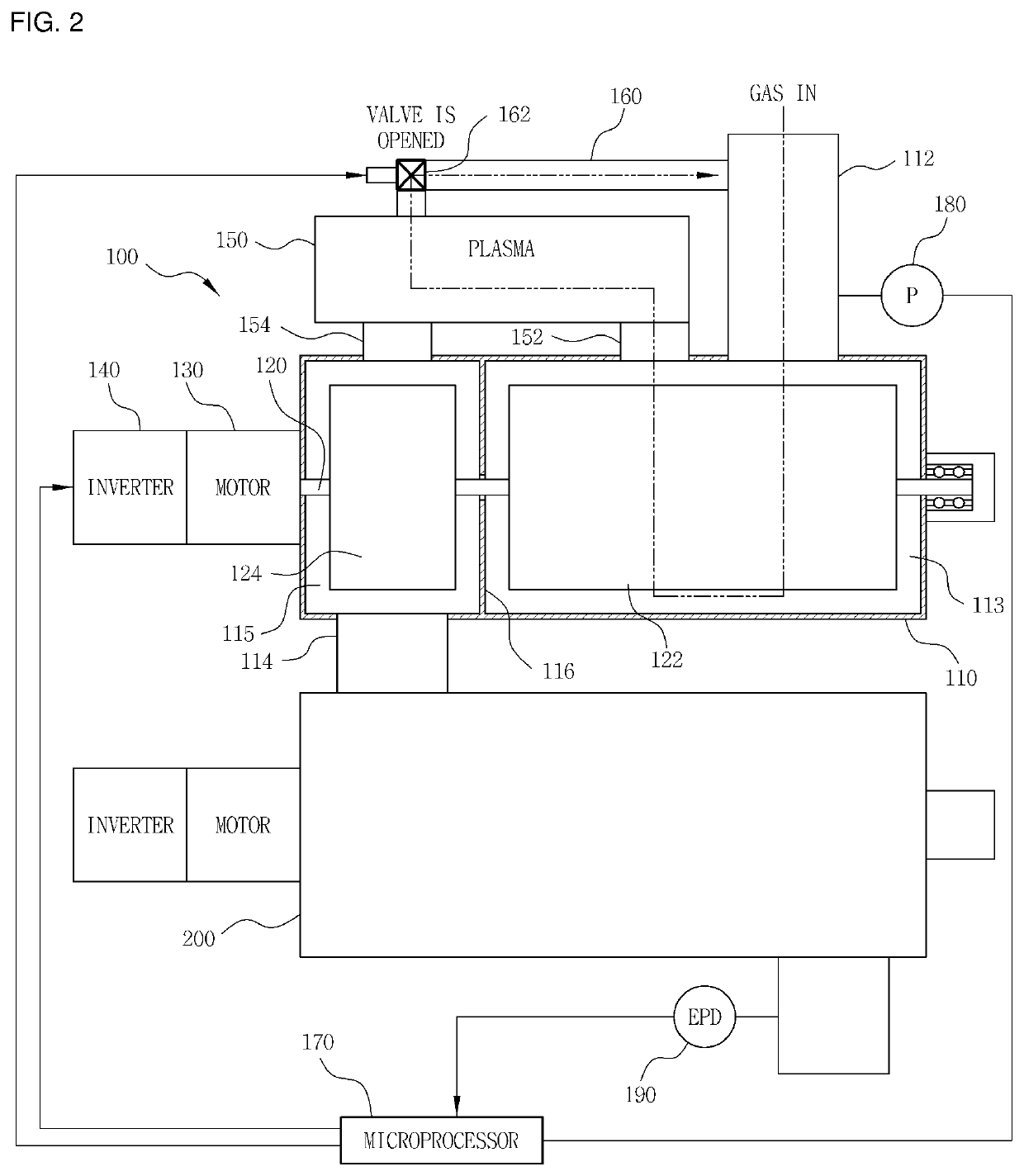
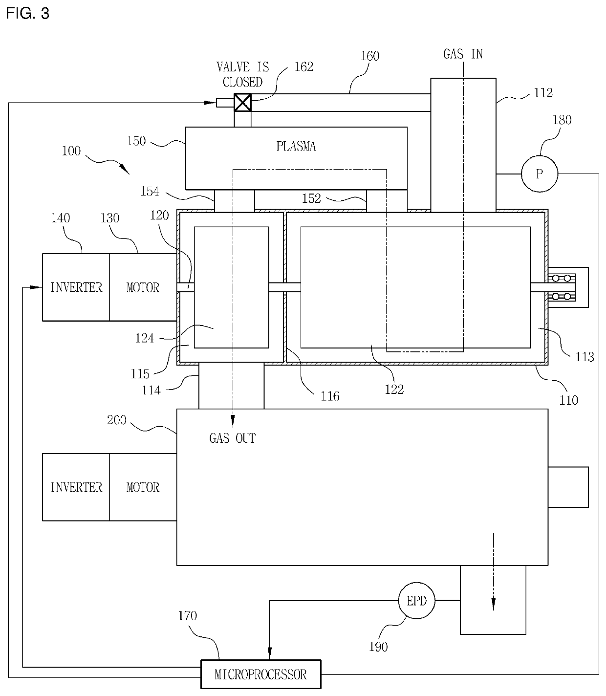
[0051]FIGS. 2 and 3 are schematic diagrams illustrating a system for treating exhaust fluid from semiconductor manufacturing equipment according to the present invention, and reference numeral 100 indicates a booster pump of a vacuum pump.

[0052]The booster pump 100 employs a multi-stage pump in which a plurality of rotors is mounted on ...


PUM

PropertyMeasurementUnit
rotational speedaaaaaaaaaa
pressureaaaaaaaaaa
suction pressureaaaaaaaaaa

Abstract

Disclosed is a system for treating exhaust fluid from semiconductor manufacturing equipment in which cleaning gases decomposed by a plastic apparatus alternately flow towards a front rotor region (a main rotor unit) and a rear rotor region (a subsidiary rotor unit) of a booster pump and then flow towards a dry pump, and thus uniformly react with process byproducts present throughout the whole area in a vacuum pump including the booster pump and the dry pump so as to improve removal efficiency of the process byproducts. Further, the retention time of the cleaning gases decomposed by the plasma apparatus in the vacuum pump is increased by adjusting the pressure in the pump with the rotational speed of a motor, and thus the reaction time of the cleaning gases with the process byproducts is increased, so as to further improve removal efficiency of the process byproducts, such as SiO2 powder.

Description

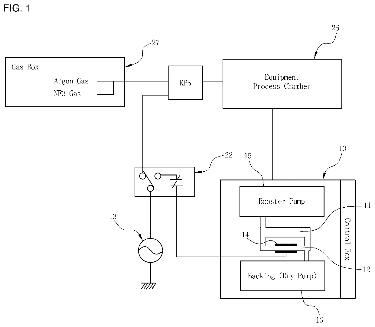
CROSS-REFERENCE TO RELATED APPLICATION[0001]This application claims under 35 U.S.C. § 119(a) the benefit of priority to Korean Patent Application No. 10-2020-0125662 filed on Sep. 28, 2020, the entire contents of which are incorporated herein by reference.BACKGROUND(a) Technical Field[0002]The present disclosure relates to a system and method for treating exhaust fluid from semiconductor manufacturing equipment. More particularly, it relates to a system and method for treating exhaust fluid from semiconductor manufacturing equipment in which a plasma apparatus is installed on a vacuum pump for treatment of the exhaust fluid discharged from the semiconductor manufacturing equipment and a bypass pipe configured to recycle a part of the fluid passing through the plasma apparatus to an inlet is also installed thereon, so as to greatly improve decomposition and treatment efficiency of process byproduct gases flowing along the inner pipes of the vacuum pump.(b) Background Art[0003]In gene...

Claims


Application Information

Patent Timeline
Patent Type & Authority Applications(United States)
IPC IPC(8): B01D53/92B01D53/38B01D53/32C23C16/44
CPCB01D53/92B01D53/38B01D2259/818C23C16/4412B01D2258/0216B01D53/32B01D2257/2066B01D2257/204B01D2257/2047B01D2257/2027B01D53/68B01D53/346B01D2256/18C23C16/4405H01J37/32844H01J37/32834H01J37/32862F04D29/701F04D19/04F04B37/14F04B41/06F04B49/24F04B17/03F04B49/20Y02C20/30F04C25/02F04C18/126F04C23/001F04C2220/12F04C2220/30F04C28/08F04C2240/403
Inventor LEE, IN CHEOL
Owner PLAN
Learn More