
Method for preparation of a supported noble metal-metal alloy composite, and the obtained supported noble metal-metal alloy composite

Pending Publication Date: 2022-05-12
KEMIJSKI INST
View PDF0 Cites 0 Cited by
  • Summary
  • Abstract
  • Description
  • Claims
  • Application Information

AI Technical Summary

Benefits of technology

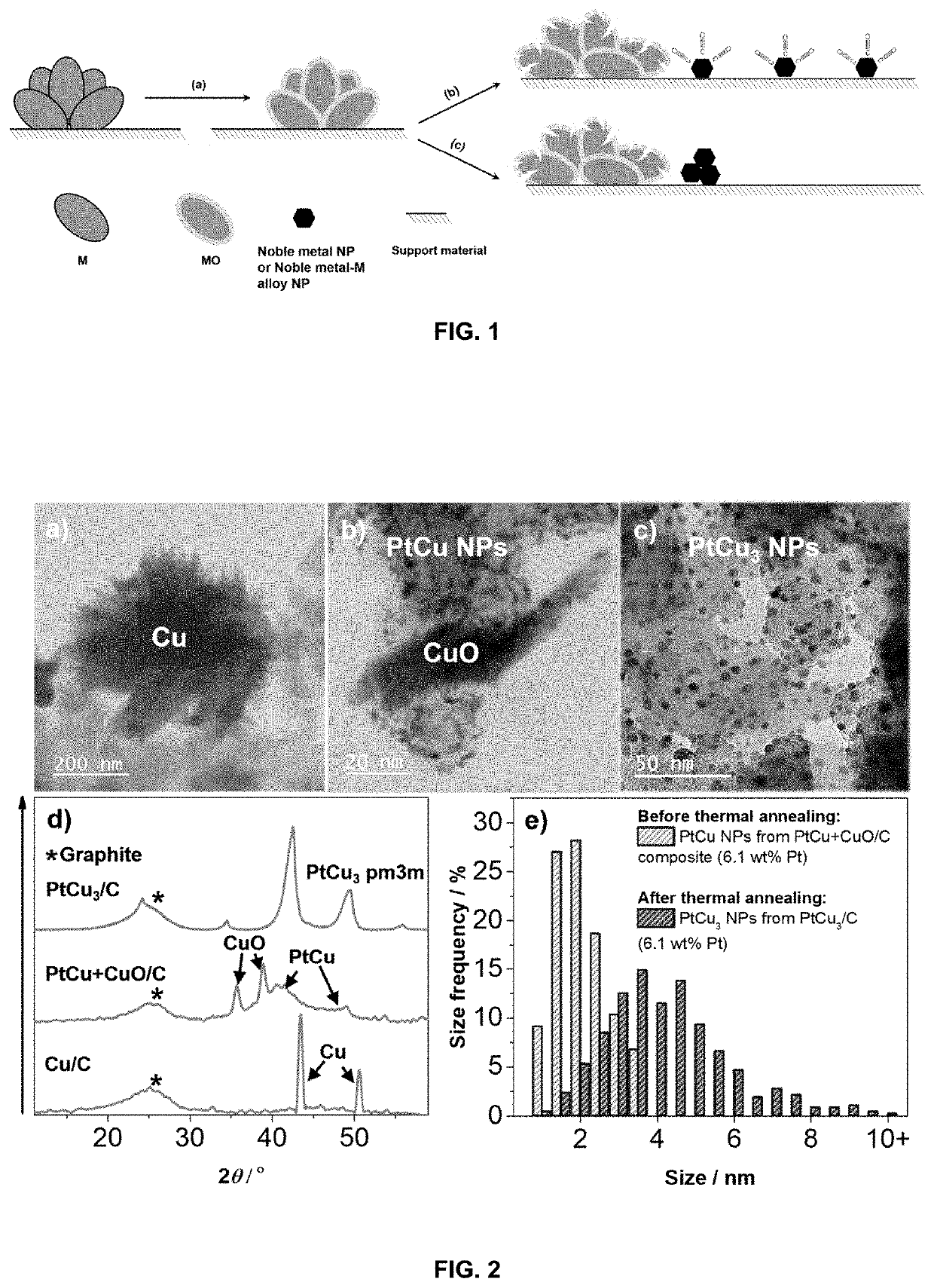
The present invention is a double passivation method for producing noble metal nanoparticles on a support particle using a chemical vapor deposition (CVD) process. The first passivation involves spontaneous growth of a passivating oxide layer on exposed surface metal particles, which lowers electron conductance and maintains ionic conductivity. The second passivation involves using an adsorptive gas to shield early stage formed noble metal nanoparticles and promote new particle formation on the support particle. This method results in stable and highly dispersed noble metal nanoparticles on the support particle, which are not core-shell type particles.

Problems solved by technology

Prior to wide adoption by large industries, including the automotive sector, PEMFC technology needs first to address many inherent issues related to the electrocatalyst such as the high overpotential of the cathode oxygen reduction reaction (ORR) that demands high Pt loadings which, in turn, leads to high costs.
While this type of synthesis enables a precise control over the shape of nanoparticles (i.e., allows creation of shape-controlled octahedral nanoparticles, nanoframes, nanowires, etc.), it also includes several inherent limitations such as (i) limitation to a milligram scale range per batch; (ii) long synthesis times; (iii) elevated temperatures or also elevated pressures (e.g. solvothermal synthesis); (iv) high cost of acetylacetonate Pt precursor; (v) usage of expensive complex organic solvents and surfactants that need to be removed via additional synthesis steps; (vi) the sequential nature of nanoparticles synthesis and their subsequent deposition on the supporting material; and (vii) any thermal annealing processes can induce undesired morphological changes at already mild temperatures and thus a loss of desired nanocrystals facets.
This makes the GD-type synthesis method, similarly to polyol-type synthesis, rather difficult to scale to an industrially relevant level.

Method used


Image

  • Method for preparation of a supported noble metal-metal alloy composite, and the obtained supported noble metal-metal alloy composite
  • Method for preparation of a supported noble metal-metal alloy composite, and the obtained supported noble metal-metal alloy composite
  • Method for preparation of a supported noble metal-metal alloy composite, and the obtained supported noble metal-metal alloy composite

Examples


examples

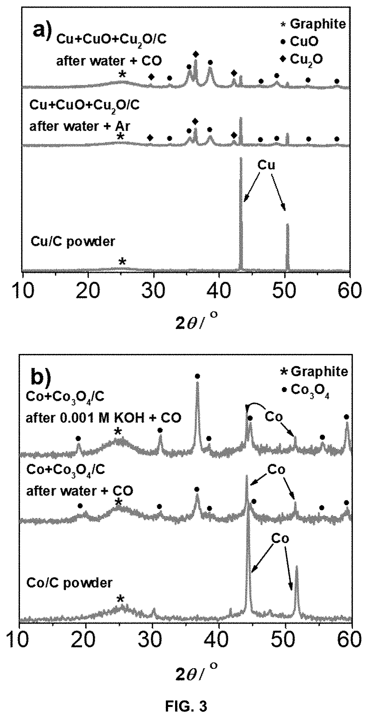
[0103]The present invention is exemplified in following Examples 1-17 by the Pt-M alloy system, wherein M is Cu, Ni or Co, and noble metal is Pt. In the said Examples commercial carbon supports of Vulcan XC72, Ketjen Black EC300J, Printex® XE2 and Ketjen Black EC600J were used, which are all carbon black materials, with BET surface area between 250 and 1400 m2 / g. The Examples also includes support materials reduced graphene oxide and TiOxNy. The following examples should not be understood as limiting for the present invention as the noble metal Pt may be alloyed with other less noble metals, M, and the support material can be any other support material as defined above.

[0104]In the present Pt-M alloy embodiment, the strong interaction between CO (carbon monoxide) gas and Pt is used as a capping agent restricting Pt nanoparticles to grow during the GD reaction. This approach not only results in synthesis of very small and well dispersed nanoparticles, but is also very energy efficien...

example 1

[0127]1-6 grams of Cu / C (C carbon black with a BET surface area of 250 m2 / g) with 25.5 wt % Cu was suspended in 100 mL (200 mL for 6 grams batch) of ultrapure water in a two neck round-bottom flask. The suspension was placed on an ultrasound bath (Ultrasound bath Iskra Sonis 4) for 3 minutes for degassing. Afterwards, the suspension was purged with Ar for 45 minutes. The suspension was then bubbled with CO gas for 15 minutes while stirring with a magnetic stirrer at 900 rpm to achieve saturation. After 15 minutes of bubbling with CO (g), 11 mL of 0.1 M K2PtCl4 (Apollo scientific) per gram of Cu / C was added with a syringe pump (WPI sp100i, flow 160 mL / h) continuously while purging the reaction mixture with CO (g). After entire Pt precursor was added to the reaction mixture, the suspension was filtered and redispersed in fresh ultrapure water. After 15 minutes of mixing, the suspension was once again filtered and the process was repeated in total 3 times. After the last filtration, th...

example 2

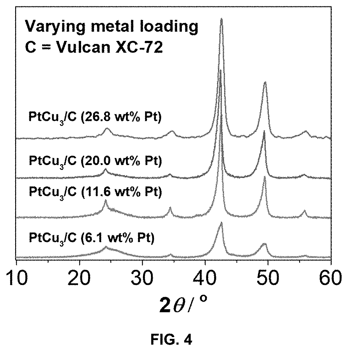
[0128]2 grams of Cu / C (C: carbon black with a BET surface area of 250 m2 / g) with 9.3 wt % Cu was suspended in 250 mL of ultrapure water in a two neck round-bottom flask. The suspension was placed on an ultrasound bath (Ultrasound bath Iskra Sonis 4) for 3 minutes (degassing). Afterwards, the suspension was purged with CO for 15 minutes while stirring with a magnetic stirrer at 900 rpm to achieve saturation. After 15 minutes of bubbling with CO, 3.3 mL of 0.1 M K2PtCl4 (Apollo scientific) per gram of Cu / C was added with a syringe pump (WPI sp100i, flow 160 mL / h) continuously while purging the reaction mixture with CO. The rest of the synthesis was the same as in the case of Example 1. PtCu3 / C electrocatalyst with 6.1 wt % Pt and 8.6 wt % Cu was collected at the end.


PUM

PropertyMeasurementUnit
Electrical conductivityaaaaaaaaaa
Solubility (mass)aaaaaaaaaa
Electrical conductoraaaaaaaaaa

Abstract

The present invention concerns a double passivation galvanic displacement (GD) synthesis method for production of high performance, supported noble metal-M alloy composite material, where M is an electrochemically less noble metal, compared to the noble metal, the supported noble metal-M alloy composite material obtained by the synthesis, and the use of such composite material as electrocatalyst material.

Description

TECHNICAL FIELD[0001]The present application relates to a method for preparation of supported noble metal-metal alloy composite materials by a galvanic displacement synthesis process, and the supported noble metal-metal alloy composite materials obtained by the process. The present application especially relates a synthesis method for production of high performance supported noble metal-M alloy electrocatalysts composite material, the supported noble metal-M alloy electrocatalysts composite material obtained by the method and the use thereof.BACKGROUND ART[0002]Proton Exchange Membrane fuel cells (PEMFC), which are able to efficiently convert hydrogen to electrical energy with the only side product being water (and heat), will play an important part in the future sustainable energy solutions. Prior to wide adoption by large industries, including the automotive sector, PEMFC technology needs first to address many inherent issues related to the electrocatalyst such as the high overpot...

Claims


Application Information

Patent Timeline
IPC IPC(8): B22F1/054B82Y40/00B22F1/18
CPCB22F1/054B82Y30/00B22F1/18B82Y40/00H01M4/921H01M4/926Y02E60/50H01M2008/1095B22F2301/10B22F2301/25B22F2302/40B22F2304/054
Inventor GATALO, MATIJAHODNIK, NEJCBELE, MARJANGABERSCEK, MIRAN
Owner KEMIJSKI INST
Learn More