A patient tuned ophthalmic imaging system with single exposure multi-type imaging, improved focusing, and improved angiography image sequence display

a multi-type imaging and patient-tuned technology, applied in the field of ophthalmic imaging systems, can solve problems such as the difficulty of patient stillness during imaging, and achieve the effect of improving focus and functionality

Pending Publication Date: 2022-05-26
CARL ZEISS MEDITEC AG +1
View PDF0 Cites 2 Cited by
  • Summary
  • Abstract
  • Description
  • Claims
  • Application Information

AI Technical Summary

Benefits of technology

[0007]The above objects are met in a system / method with improved focus and functionality. Firstly, a focus mechanism based on the difference between consecutive line scans effectively converts broad lines into thin lines for purposes of determining a defocus measure. These thin lines may further be used to determine the topology of the retina.
[0012]To further improve FA and ICGA examinations, the present system provides for simplified capturing of a sequence of FA or ICGA images. The present system provides a very high dynamic range such that an operator does not need to adjust image brightness while capturing an FA or ICGA image sequence. The raw images are stored and relative brightness information among the images in the sequence may be determined from the raw data and accurately provided to a user, for example, as a plot. Additionally, the operator is provided with options for brightening the stored images for viewing while maintaining the relative brightness between the acquired sequence of images.
[0014]Other improvements in the present system include various mechanisms for taking multiple imaging modalities with a single capture command. This not only reduces the amount of time required for an examination, but also provides additional information that may be used for additional diagnosis. For example, along with every color image, the system may automatically capture an IR image, which can enhance the visibility of some tissues.

Problems solved by technology

Further complicating ophthalmic imaging is that it can be difficult for a patient to remain still during imaging.
This can be particularly problematic when multiple different types of images are needed or when the patient has an aversion to high intensity illumination, e.g., photophobia.

Method used


Image

  • A patient tuned ophthalmic imaging system with single exposure multi-type imaging, improved focusing, and improved angiography image sequence display
  • A patient tuned ophthalmic imaging system with single exposure multi-type imaging, improved focusing, and improved angiography image sequence display
  • A patient tuned ophthalmic imaging system with single exposure multi-type imaging, improved focusing, and improved angiography image sequence display

Examples


Embodiment Construction

[0056]There are various types of ophthalmic imaging systems, such as discussed below in sections Fundus Imaging System and Optical Coherence Tomography (OCT) Imaging System. Aspects of the present invention(s) may apply to any, or all, such ophthalmic imaging systems. In general, the present invention provides various enhancements to the operation and user interface of an ophthalmic imaging system.

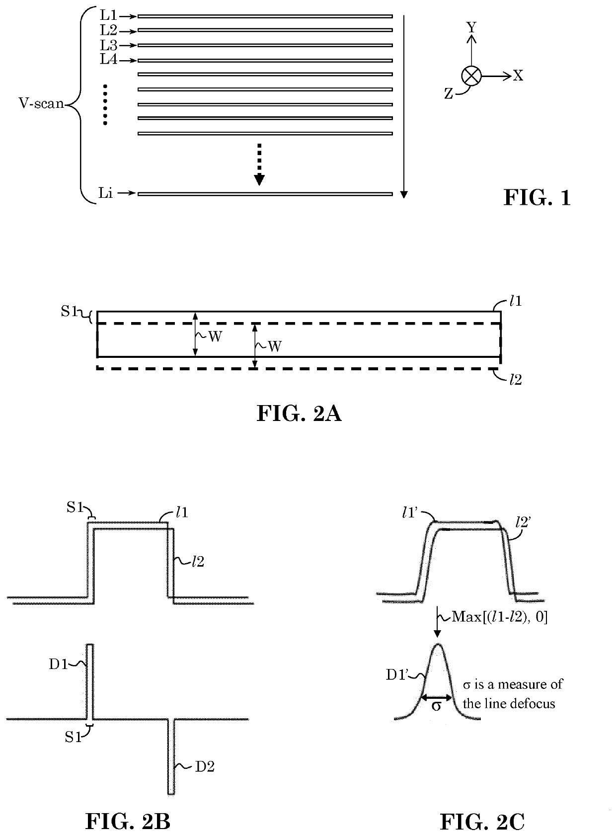
[0057]Thin Line Scanning for Focus and Depth Analysis

[0058]One aspect of the present invention provides improved methods of determining image measures for focusing application (e.g., autofocus) and deconvolution applications (e.g., topography). As a particular example, the present enhanced focusing (and deconvolution) techniques and applications are described as applied to an ophthalmic imaging systems that use a linear light beam, such as a broad line, that is scanned across a sample to create a series of image-segments that can be combined to construct a composite image of the sample, bu...


PUM


Abstract

An ophthalmic imaging system provides an automatic focus mechanism based on the difference of consecutive scan lines. The system also provides of user selection of a focus point within a fundus image. A neural network automatically identifies the optic nerve head in an FA or ICGA image, which may be used to determine fixation angle. The system also provides additional scan tables for multiple imaging modalities to accommodate photophobia patients and multi-spectrum imaging options.

Description

FIELD OF INVENTION[0001]The present invention is generally directed to the field of ophthalmic imaging systems. More specifically, it is directed to techniques for facilitating user operation of ophthalmic imaging system.BACKGROUND[0002]There are various types of ophthalmic examination systems, including ophthalmoscopes, Optical Coherence Tomography (OCT), and other ophthalmic imaging systems. One example of an ophthalmic imaging is slit-Scanning or Broad-Line fundus imaging (see for example U.S. Pat. Nos. 4,170,398, 4,732,466, PCT Publication No. 2012059236, US Patent Application No. 2014 / 0232987, and US Patent Publication No. 2015 / 0131050, the contents of all of which are hereby incorporated by reference), which is a promising technique for achieving high resolution in vivo imaging of the human retina. The imaging approach is a hybrid between confocal and widefield imaging systems. By illuminating a narrow strip of the retina while scanning, the illumination stays out of the viewi...

Claims


Application Information

Patent Timeline
Patent Type & Authority Applications(United States)
IPC IPC(8): A61B3/12A61B3/14A61B3/00G06T7/00
CPCA61B3/12A61B3/14A61B3/0008G06T7/0014G06T2207/30041G06T2207/20224G06T2207/10064G06T2207/10048G06T2207/20084A61B3/1241A61B3/0025A61B3/102G06T7/0012A61B5/14555G06T2207/10024G06T2207/10101G06T2207/10152G06T2207/20081G06T2207/30168G06T7/571G06T2207/20101G06T2200/24G06T7/73
Inventor LEAHY, CONORSCHMIDT, JEFFREYBROCK, KEITHKULKARNI, PRIYANOLAN, DAVIDO'HARA, KEITHEVERETT, MATTHEW J.CHEN, MICHAELOMLOR, LARSMANIVANNAN, NIRANCHANADURBIN, MARY
Owner CARL ZEISS MEDITEC AG
Why Eureka
Try Eureka