Dehumidification system with variable capacity

a technology of dehumidification system and variable capacity, which is applied in the direction of lighting and heating apparatus, heating types, domestic applications, etc., can solve the problems of affecting the efficiency of the system, etc., and achieves the effect of high efficiency

Active Publication Date: 2022-06-09
COIL RES LLC
View PDF0 Cites 3 Cited by
  • Summary
  • Abstract
  • Description
  • Claims
  • Application Information

AI Technical Summary

Benefits of technology

[0007]A dehumidification system for plant matter and other agricultural products in an environmentally controlled room is provided with a head unit and one or more modular dehumidifier units. Each modular dehumidifier unit may include a coil set with a cooling and a heating coil. The use of modular coil sets permits the dehumidification system to be scaled by activating / deactivating individual coil sets. This allows the system to function at different capacities and to operate at high efficiency at each of the different capacities. The dehumidification system includes a cooling refrigerant circuit that moves cooled refrigerant through the cooling coils to cool the air and / or dehumidify the air through condensation and a heating refrigerant circuit that moves heated refrigerant through the heating coils to heat the air, for example, to return heat energy to offset the heat loss in dehumidification or to heat the room. The modular coil sets are connected to the head unit so that the cooling coils of different coil sets are arranged in parallel with one another and the heating coils of different coil sets are arranged in parallel with one another. The number of modular coil sets installed in a system can be selected to provide the system with the desired maximum capacity, and the capacity of the system at any given time can be established by activating the appropriate number of coils or coil sets.
[0008]In one embodiment, the dehumidification system includes a control system capable of operating the system at different capacity levels by varying the number of active modular coil sets to achieve the desired level of dehumidification and operating each active coil within optimized parameters. For example, the flow rates and, in some cases, the refrigerant temperatures for the cooling refrigerant circuit and heating refrigerant circuit can be selected to provide optimized efficiency for the active cooling and heating coils. The use of modular coils arranged in parallel helps to provide enhanced refrigerant / coil performance and can result in reduced back-pressure.
[0017]The dehumidification system of the present invention includes a head unit capable of receiving one or more modular coil sets, which allows the maximum capacity of the system to be easily varied by adding and removing modular coil sets. The number of modular coil sets installed in the system can be selected to provide the system with the desired maximum capacity, and the capacity if the system at any given point in time can be set by activating the appropriate number of coils or coil sets. The wide capacity range of the dehumidification system allows it to be used for a wide range of activities, such as drying, curing, dehydrating, maintaining humidity and other activities made available through control of temperature and / or humidity (e.g. for controlled storage applications). The use of separate cooling and heating circuits allows the system to vary the operating parameters of the cooling and heating stages separately, thereby providing a greater range of control over the system. The cooling and heating coils are arranged in parallel, which facilitates selective activation of individual coils, provides enhanced refrigerant and enhanced coil performance and results in reduced back-pressure in the refrigerant circuits. The use of modular dehumidification units facilitates installation as the modular units can be pre-assembled with the ability for simple field installation to an existing dehumidification system. Further, the use of pass-through supply and return line extensions in each modular dehumidification system allows the modular dehumidification units to be installed in sequence while still providing a parallel refrigerant circuit arrangement for the cooling coils and a parallel refrigerant circuit arrangement for the heating coils. In operation, the control system allows the capacity of the system to be adjusted by activating only the desired number of modular coils or coil sets while maintaining efficient operation at each of the different capacities. In particular, the flow of refrigerant to one or more modular units can be shut off while maintaining the flow of refrigerant to one or more other modular units. Because the system includes separate heating and cooling circuits, the system is capable of dehumidifying with or without heating or cooling, and also capable of heating or cooling without dehumidification.
[0018]The present invention provides significant improvements over conventional dehumidification systems that include one large coil (e.g. 25 tons coil), particularly in applications where moisture removal requirements vary materially over time. With conventional systems, the large coil generally needs to run at near full refrigerant coil flow to deal with the large amount of heat offset and to maintain sufficiently cool coil surfaces to remove any meaningful amount of moisture. If refrigerant flow through a large coil is materially reduced, the coil surface temperature will typically be too warm to remove any moisture. So, even when only a small amount of moisture removal is desired, a conventional system with a single large coil has to run at near full glycol flow rates. On the other hand, the present invention provides modular coils that can be selectively activated or deactivated to effectively vary coil capacity to match with the desired moisture removal level. This significantly reduces energy usage and assures that all activated coil surfaces can be fully utilized thru the whole range of room requirements.

Problems solved by technology

However, the cooling coil cycling on and off in this configuration results in swings of the dew point in the room and wastes energy via reheat (i.e., simultaneously cooling and heating the air in the room).
Moreover, as Pw is dependent on dew point, P*w is dependent on dry bulb temperature, and the vapor pressure of any given dryable / curable product is unique, these dry rooms are typically not suitable for use with widely-varying products or changing atmospheric conditions.
If available water is removed from such a product too rapidly (e.g. from vapor pressure in the dry room being too low compared to a vapor pressure within the product), the outer layer of the product may become too dry, in turn reducing the rate at which moisture can leave the center of the product, or trapping moisture in the center of the product all together.
Unfortunately, conventional EC rooms are limited in application due to constraints on the ranges of conditions that may be employed.
In particular, the various HVAC and other components (e.g. heat pump dryers) employed in EC rooms, while often very effective when operated individually within a preferred range of conditions (e.g. within a particular temperature range, humidity range, etc.), are typically inefficient when operated outside of the preferred range.
Moreover, these same components are frequently counter-productive when employed simultaneously.
Moreover, as the refrigeration capacity of the heat pumps are typically selected based on the size and maximum product loading of a given drying chamber, these systems are often both incapable of being scaled down for operations with a reduced-loading size (e.g. to maintain cost / load, reduce pump strain, etc.), and unable to accommodate scale-up (e.g. for increased drying capacity) without partial, or sometimes complete, replacement of refrigerating components.
Moreover, conventional refrigeration systems are limited in terms of the RH ranges that may be realized during operation, thus placing constraints on both atmospheric temperature and moisture loads within the EC room.
), which can lead to the formation of ice on the coils, reduced moisture removal capacity, etc., and necessitate the use of remedial procedures / components (e.g. defrost cycles, tandem coils, brine solutions etc.), which are often burdensome and expensive, to maintain proper function.

Method used


Image

  • Dehumidification system with variable capacity
  • Dehumidification system with variable capacity
  • Dehumidification system with variable capacity

Examples


Embodiment Construction

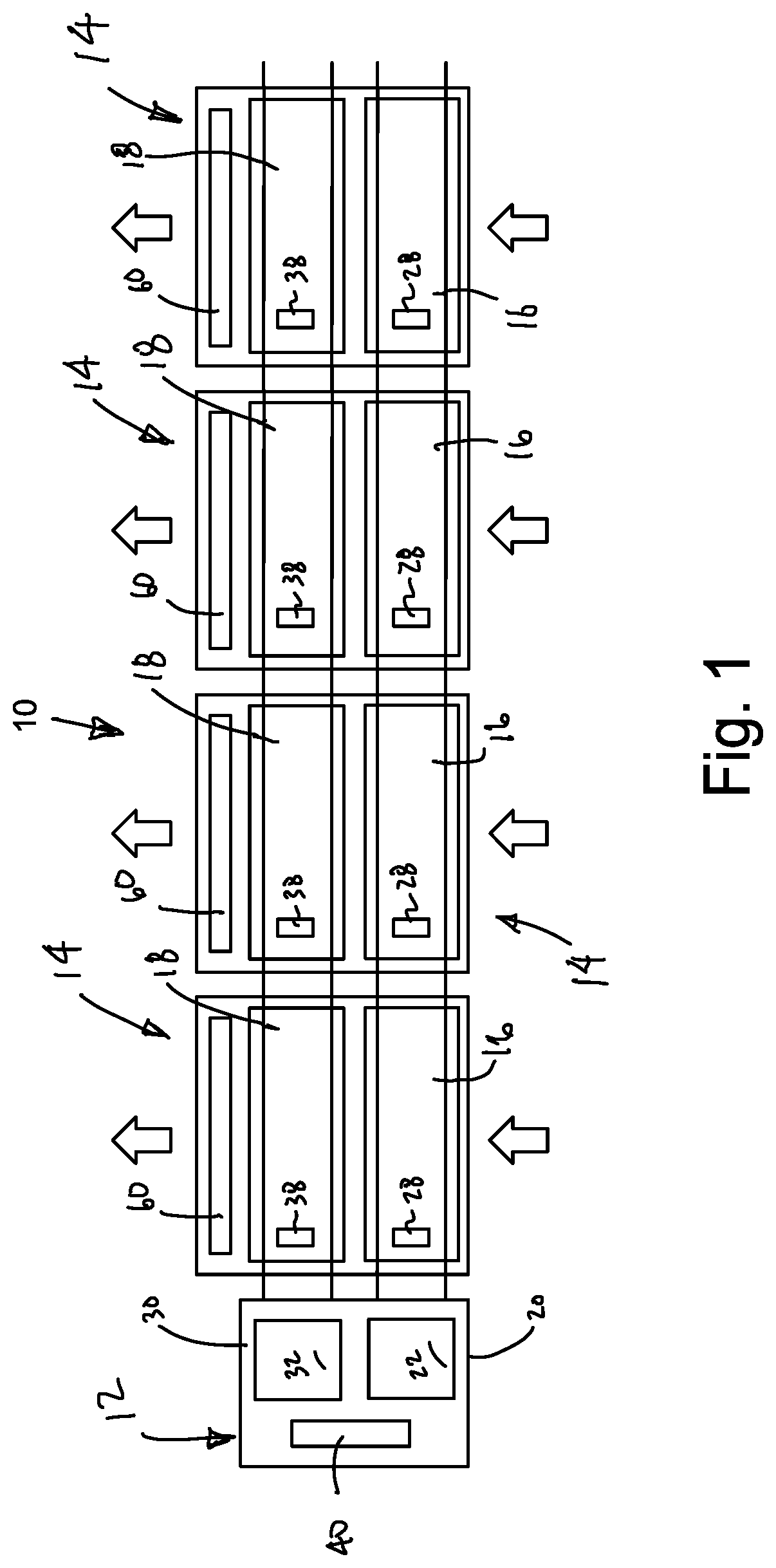
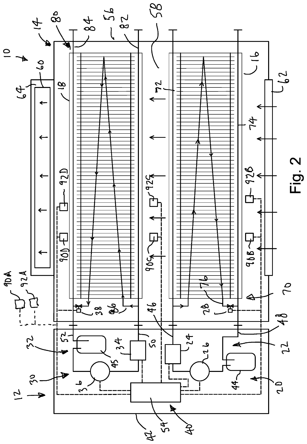
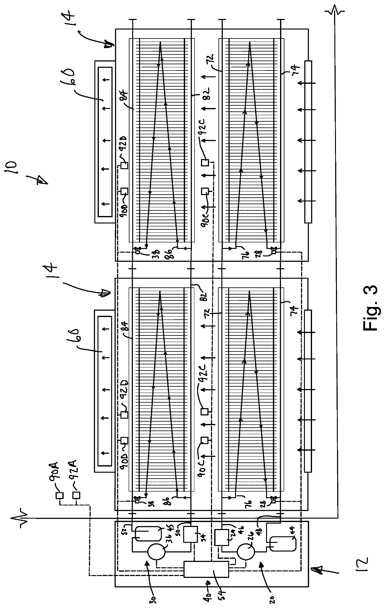
[0026]A dehumidification system in accordance with one embodiment is illustrated in FIG. 1 and generally designated 10. The dehumidification system 10 is configured for use with an environmentally controlled room and includes a cooling refrigerant circuit 20 that circulates cooled refrigerant through one or more modular cooling coils and a heating refrigerant circuit 30 that circulates heated refrigerant through one or more modular heating coils. The cooling refrigerant circuit 20 may be used to cool the air within the room and / or to dehumidifying the air through condensation. The heating refrigerant circuit 30 may be used to heat the air, for example, to offset the heat loss associated with dehumidification and / or to heat air within the room.

[0027]In the illustrated embodiment, the dehumidification system 10 includes a head unit 12 and a plurality of modular dehumidifier units 14. The head unit 12 includes a cooling refrigerant subcircuit 22 with a chiller 24 to cool a supply of re...


PUM


Abstract

A multi-use system for influencing organic matter in an environmentally controlled room is provided with a modular dehumidification system. The modular dehumidification system includes a head unit, with separate cooling and heating subcircuits, and multiple modular dehumidifier units. Each modular dehumidifier unit has a cooling coil operable to cool and / or dehumidify the air and a heating coil operable to heat the air, for example, to raise room temperature and / or offset heat loss arising during dehumidification. The cooling coils are connected to the head unit in parallel to one another and the heating coils are connected to the head unit in parallel to one another. The number of modular dehumidifier units installed in the system is selected to provide the system with the desired maximum capacity. The control system may be configured to activate the appropriate number of cooling and heating coils, and to control the operation of each active coil.

Description

FIELD OF THE INVENTION[0001]The present invention relates to dehumidification systems for organic material, for example, in drying, curing, dehydration and storage of harvested plant matter and agricultural products.BACKGROUND OF THE INVENTION[0002]Environmentally Controlled (EC) rooms are commonly used to store fruits, vegetables, and other commodities that benefit from storage in environments where certain factors, such as temperature and atmospheric composition, can be controlled to extend the life of such items. EC rooms typically utilize systems for monitoring atmospheric conditions inside of a gastight space (e.g. temperature, gas levels, humidity, etc.), as well as systems for controlling such conditions to maintain the atmosphere at one or more desired set points. For example, EC rooms typically employ various heating, ventilation, and air conditioning (HVAC) components, such as heaters, blowers and fans, humidifiers, dehumidifiers, etc.[0003]In addition to use as storage sp...

Claims


Application Information

Patent Timeline
Patent Type & Authority Applications(United States)
IPC IPC(8): F24F3/14
CPCF24F3/1405F24F2003/1452F24F2221/36
Inventor SCHAEFER, JAMES C.LARAWAY, MICHAEL C.COOPER, THOMAS L.HANKAMP, NICHOLAS R.
Owner COIL RES LLC
Why Eureka
Try Eureka