Insulating wire with high thermal resistance and resistant to partial discharges and wire drawing process

a technology of partial discharge and insulation wire, which is applied in the manufacture of insulating cables, cables, insulating conductors/cables, etc., can solve the problems of motor insulation systems and reduce service life, and achieve high thermal class, high thermal resistance, and optimized insulation properties.

Pending Publication Date: 2022-06-23
WEG EQUIP ELETRICOS SA
View PDF0 Cites 0 Cited by
  • Summary
  • Abstract
  • Description
  • Claims
  • Application Information

AI Technical Summary

Benefits of technology

[0016]The invention is related to the manufacturing of wires with optimized insulation properties, providing an insulating wire and the wire drawing process to produce this insulating wire. The wire is insulated with three layers: base layer (2), middle layer (3) and top layer (4), wherein these layers wrap around the conducting wire (1) in this order. The wire manufacturing process comprises the following steps: a) Primary drawing; b) Final drawing and c) enameling. These steps are carried out in line and the enameling is conducted preferably with a specific number of dies for each layering. This process guarantees a wire with a triple layer enamel that provides high resistance to partial discharges, a high thermal class and high resistance to abrasion, thus, increasing the service lifetime of the wire in demanding motor applications when high thermal, high mechanical and high electrical resistance are required.

Problems solved by technology

When such applications are carried out in conjunction with variable speed drives (static frequency converters), in addition to the previously mentioned thermal requirements, there are additional dielectric stresses potentially harmful to the motor insulation system, due to the phenomena of transmission lines and traveling waves that can degrade the winding in an accelerated manner, thus reducing its service life, especially when the motor is powered by long cables.
However, the aim of US20130099621 is to provide the resistance against partial discharges in the electrical insulation system, without any technical solution for improving thermal and mechanical properties of the wire at the same time.

Method used


Image

  • Insulating wire with high thermal resistance and resistant to partial discharges and wire drawing process
  • Insulating wire with high thermal resistance and resistant to partial discharges and wire drawing process
  • Insulating wire with high thermal resistance and resistant to partial discharges and wire drawing process

Examples


Embodiment Construction

[0024]In the following description, for the purpose of explanation, numerous specific details are set forth in order to provide a thorough understanding of the present disclosure. It will be apparent, however, that embodiments may be practiced without these specific details. Embodiments are disclosed in sections according to the following outline:

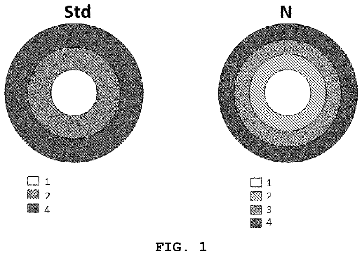
[0025]The present invention comprises a triple enameled magnetic wire, that is a wire whose insulation consists of three insulating layers. The three insulating layers are nominated as base layer (2), middle layer (3) and top layer (4), wherein these layers wrap around the conducting wire (1) in this order.

[0026]The conducting wire (1) is made of a conductive material. Examples of suitable materials include, but are not limited to, aluminum, copper, brass, silver, etc. In one preferable embodiment the said conducting wire (1) is made by aluminum, preferably made by an aluminum alloy, most preferably made by a 1350 alloy according to ASTM B-...


PUM

PropertyMeasurementUnit
temperatureaaaaaaaaaa
diameteraaaaaaaaaa
diameteraaaaaaaaaa

Abstract

A manufacturing of wires with optimized insulation properties, providing an insulating wire and the wire drawing process for producing it. The wire enamel has three layers: base layer (2), middle layer (3) and top layer (4), wherein these layers wrap around the conducting wire (1) in this order. The wire drawing process is carried out by a) Primary drawing; b) Final drawing and c) Enameling process carried out in line, wherein the enameling is conducted preferably with a specific number of dies for each layer. The process and composition conditions of the wire allowed to provide a triple layer wire that presents high resistance to partial discharges, high thermal class and high resistance to abrasion, thus, increasing the service lifetime of the wire in demanding motor applications when high thermal, high mechanical and high electrical resistance are required.

Description

CROSS-REFERENCE TO RELATED APPLICATIONS[0001]This application claims the benefit of U.S. Provisional Application No. 63 / 129,922 filed on Dec. 23, 2020, the contents of which is incorporated herein by reference.TECHNICAL FIELD[0002]The wider technical field of the present disclosure is related to the manufacturing of cables, conductors, insulators, and the selection of materials for their conductive, insulating or dielectric properties, more specifically the field is related to the disposition of insulation in these components, and even more specifically for dispositions comprising two or more layers of insulation having different electrical, mechanical, chemical and / or thermal properties.BACKGROUND OF THE INVENTION[0003]The approaches described in this section are approaches that could be pursued, but not necessarily approaches that have been previously conceived or pursued. Therefore, unless otherwise indicated, it should not be assumed that any of the approaches described in this ...

Claims


Application Information

Patent Timeline
Patent Type & Authority Applications(United States)
IPC IPC(8): H01B7/02H01B13/00H01B13/06H01B13/16
CPCH01B7/0225H01B13/16H01B13/065H01B13/0016H01B7/0291H01B3/105H01B3/306H01F5/06H01B3/302H01B3/421H01B3/305H01B3/301H01B1/026H01B1/023H01B1/02
Inventor LOURENCO, RENATOMEDEIROS, CRISTIANEDE LIMA PIRES, WALDIBERTOGOMEZ MELLO, HUGO GUSTAVO
Owner WEG EQUIP ELETRICOS SA
Why Eureka
Try Eureka