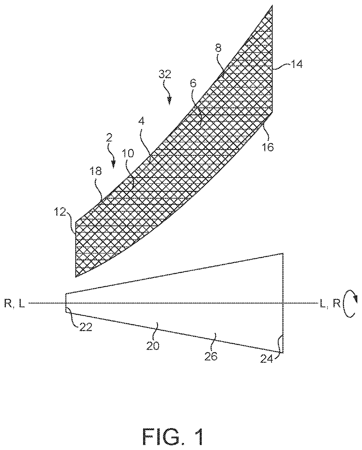
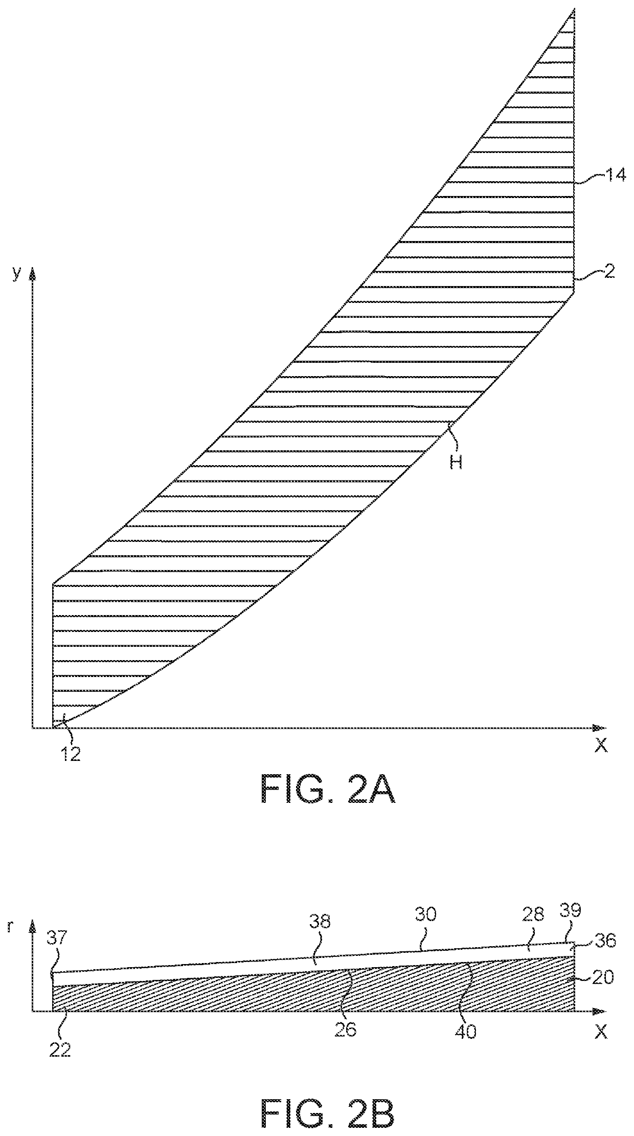
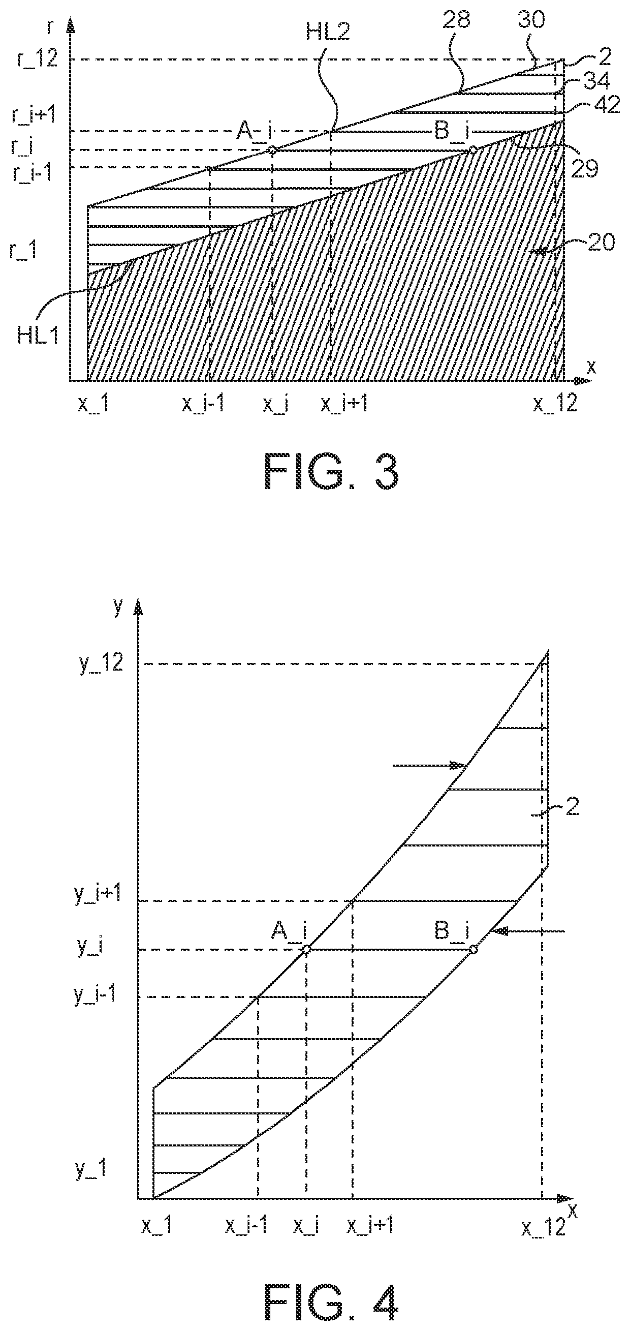
When winding a preform or prepreg, either helically using a narrow tape, or by roll wrapping a sheet aligned perpendicularly or at an inclination with respect to the mandrel, around a mandrel that has other than a cylindrical surface, i.e. a cylindrical surface provided by a circular cross-section of a given
radius extending along the entire length of the mandrel, there can be significant technical problems.
A first technical problem is that since the cross-section of the mandrel changes along the length of the mandrel, the prepreg can become skewed relative to the desired wrapping direction.
This can cause wrinkles and fibre mis-alignment to be present in the wrapped elongate tube, which can seriously degrade the mechanical performance, and
visual appearance, of the
resultant elongate tubular shaft comprised of the fibre-reinforced resin matrix composite material formed from the prepreg.
Fibre mis-alignment is a particular problem in the manufacture of non-cylindrical tubes, most particularly when product uniformity and consistency is a key performance parameter.
Another problem in the manufacture of non-cylindrical tubes having complex tube geometry is that the fibre
layers can be inadvertently bent, twisted or folded, leading to the undesired formation of wrinkles in the preform layers that are manifested as misaligned or bent fibres or even voids in the final moulded composite material product.
Moreover, wrinkles and fibre mis-alignment can lead to a lack of consistency in performance between plural tubular products.
Known manufacturing methods can encounter significant production problems in attaining such desired properties.
A second technical problem is that to accommodate changes in the geometry of the mandrel along its length, this can require a high level of manual intervention during the manufacturing process, and consequently a low level of
automation.
This increases manufacturing cost and complexity, and reduces the consistency and uniformity of plural tubular products.
A third technical problem is that such known processes can generate a high level of prepreg waste as a result of the prepreg tape or sheet having to be individually
cut or tailored to remove excess material from the mandrel, or as a result of excess material having to be removed from the tubular product following the moulding step, or as a result of the manufactured tubular products being rejected by failing to meet the desired quality.
However, elongate tubular shafts of carbon fibre composite material tend to suffer from the problem of exhibiting non-uniform properties, in particular a non-uniform wall thickness which leads to undesired variations in flexural stiffness along the shaft, in particular when the flexural force is applied in different rotational orientations around the axis of the shaft.
Tubular sports articles often need to incorporate controlled
variable thickness in order locally to control the stiffness of the article; however, it is difficult to automate a manufacturing process reliably and repeatably to manufacture such controlled
variable thickness with a high degree of uniformity and consistency for multiple products.
Although it is stated that the method of
filament winding on a frusto-
conical surface avoids
distortion that would occur if a tape were to be wound thereon with edge to edge contact instead of overlapping and that no large gaps within the wound material are formed, nevertheless the method cannot ensure accurate filament alignment for any significant length of the tubular component or for any significant number of filament windings.
This manufacturing method therefore suffers from a problem that the
diameter of the mandrel increases, the fibres in the prepreg, and therefore in the final composite material, will become progressively misaligned, causing a reduction in the mechanical properties of the component and a change in mechanical properties along the length of the component.
Furthermore, along the length of the component the angles of any fibres relative to the longitudinal axis of the mandrel, and thus of the component, vary and the fibres become progressively misaligned, or twisted, relative to the longitudinal axis with increasing
diameter of the mandrel and component.
In the pre-wound prepreg the fibre orientations may be consistently straight and accurately aligned along desired axes in the prepreg; however, in the final wound component the fibre orientations may not be consistently oriented and may not be accurately aligned along desired axes in the component.
Furthermore, there is no disclosure how accurately to manufacture a complex shape other than a geometric frustoconical tube.
This disclosure suffers from a problem that the preform has a complex specific spiral geometry and can only be used to make a specific geometric structure of a
conical shell.
Moreover, if the weft yarns have uniform spacing and uniform angular separation, then in the
conical shell the yarns become misaligned; however, if the weft yarns have variable spacing and / or variable angular separation, then although in the
conical shell the yarns can be aligned conically the preform is very complicated to weave with a variable fibre structure, and each preform can only be used to make a specific geometric shape.
There is no disclosure how in practice to make such a very complicated fabric for the preform.
Furthermore, there is no disclosure how accurately to manufacture a complex shape other than a geometric conical shell.
This disclosure suffers from a problem that the individual tube has a specific arrangement of the warp and weft fibres that can only be used to make a specific geometric structure of a variable
diameter tube.
The fabric is very complicated to weave with a variable fibre structure.
This disclosure suffers from a problem that the method is very complex.
Furthermore, there is no disclosure how accurately to manufacture a complex shape other than cylindrical or frustoconical tubular shapes from the inclined fibrous layers.
There is no disclosure how to provide fibres oriented in the longitudinal direction along a substantial length, or in particular along the entire length, of the tube.


