Electronic circuit for determination of distances between reference and data points

a technology of reference and data point, applied in the field of electronic circuits, can solve the problems of extreme difficulty in making allowance for the effects of device mismatch, inconvenient euclidean distance determination output of circuit, and difficulty in matching device characteristics

Inactive Publication Date: 2000-01-11
QINETIQ LTD
View PDF4 Cites 14 Cited by
  • Summary
  • Abstract
  • Description
  • Claims
  • Application Information

AI Technical Summary

Problems solved by technology

Using dissimilar-type FETs however makes it difficult to match device characteristics.
Differing carrier mobilities and other physical characteristics mean that extreme difficulty is met in making allowance for the effects of device mismatch.
This symmetry requires close matching of the characteristics of the p-channel and n-channel devices and if it is not achieved, the output of the circuit is not suitable for Euclidean distance determination.
It is not suitable for applications such as pattern recognition requiring a large number of distance measuring circuits.
It incorporates a number of transistors, two of which are considerably wider than the rest, which gives rise to difficulty as regards formation of large arrays.
The transistors also suffer from high power consumption when operating in their saturation region.
A similar disadvantage is apparent in the circuit described in "CMOS Selfbiased Euclidean Distance Computing Circuit with High Dynamic Range", Electronics Letters 28 (4) page 352, 1992. O. Landolt, E. Vittoz and P. Heim describe a device which outputs a representation of the function ##EQU1## for the n-dimensional vector of bi-directional currents

Method used


Image

  • Electronic circuit for determination of distances between reference and data points
  • Electronic circuit for determination of distances between reference and data points
  • Electronic circuit for determination of distances between reference and data points

Examples


Embodiment Construction

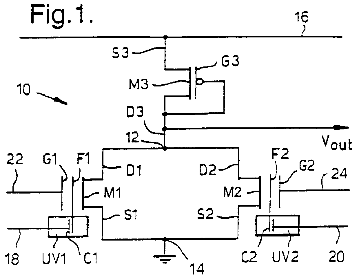
Referring to FIG. 1, there is shown an electronic circuit of the invention indicated generally by 10. The circuit 10 incorporates first and second metal-oxide semiconductor field effect transistors (MOSFETs) M1 and M2. The MOSFETs M1 and M2 are floating gate devices, generally as outlined by S M Sze in "Physics of Semiconductor Devices", 2nd Ed Wiley 1981, page 496. MOSFET M1 has a floating gate F1 and a control gate G1, and likewise MOSFET M2 has floating and control gates F2 and G2. In IEEE Electron Device Letters, Vol.12 No 3, March 1991, Thomsen and Brooke have estimated that a floating gate in a silicon MOSFET would lose charge at the rate of 0.1% in 26 years. Data represented by charge on the floating gates F1 and F2 is therefore expected to persist.

The MOSFETs M1 and M2 are parallel NMOS transistors which are used to determine the distance between a data point and a reference point. The data point is represented by input signals consisting of a voltage and its complement, the...


PUM


Abstract

PCT No. PCT/GB95/00741 Sec. 371 Date Nov. 12, 1996 Sec. 102(e) Date Nov. 12, 1996 PCT Filed Mar. 31, 1995 PCT Pub. No. WO95/30963 PCT Pub. Date Nov. 16, 1995An electronic circuit for Euclidean distance determination includes two floating gate transistors (M1, M2) connected in parallel. Voltages representing a reference point and its complement are applied to input lines (22, 24) and corresponding charges become stored on the transistors' floating gates (F1, F2). Voltages representing a data point and its complement are input to control gates (G1, G2). The transistors (M1, M2) produce a combined output current which is a quadratic or exponential function of the distance between the data and reference points according to whether the transistors are above or below threshold. The circuit (10 ) includes a diode-connected load device (M3) for deriving the square root of the output current, which is proportional to Euclidean distance when the transistors are operated above threshold. Refresh means (M44, M45) may be provided for resetting reference points. An array of circuits of the invention is employed for determination of distances between vector quantities.

Description

1. Field of the InventionThis invention relates to an electronic circuit. More particularly, although not exclusively, it relates to an electronic circuit for determination of distances between reference and data points.2. Discussion of Prior ArtElectronic circuits for determining Euclidean distances are known in the prior art. Such a circuit incorporates a stored quantity corresponding to a reference point and accepts as input a signal representing a data point. It produces a measure of the distance between the input signal and the stored quantity. Such circuits are useful in applications in which calculations of Euclidean distance would consume a substantial amount of computing capacity. In visual and speech recognition, together with other forms of pattern recognition, it is necessary to determine Euclidean distance between large numbers of input data points and each point in a large database of reference points.U.S. Pat. No. 3,864,558 discloses a pair of field effect transistors...

Claims


Application Information

Patent Timeline
IPC IPC(8): G06G7/00G06G7/20G06G7/14G06G7/12G06G7/19G06G7/24
CPCG06G7/20
Inventor MARSHALL, GILLIAN FIONACOLLINS, STEPHEN
Owner QINETIQ LTD
Why Eureka
Try Eureka