Methods for using polishing pads

a technology of polishing pads and polishing surfaces, which is applied in the direction of lapping machines, grinding devices, other chemical processes, etc., can solve the problems of uneven polishing rate, uneven surface asperities on workpieces, and production of smooth, featureless polished workpiece surfaces

Inactive Publication Date: 2000-01-25
ROHM & HAAS ELECTRONICS MATERIALS CMP HLDG INC
View PDF10 Cites 211 Cited by
  • Summary
  • Abstract
  • Description
  • Claims
  • Application Information

AI Technical Summary

Problems solved by technology

The slurry-lubricated friction between workpiece and pad results in the wearing away of surface asperities on the workpiece and the production of a smooth, featureless polished workpiece surface.
For many polishing processes, particularly those operating at high rotational speeds or pressures, inadequate slurry flow across the pad / workpiece boundary gives rise to non-uniform polishing rates, poor surface quality in the finished article and deterioration of the polishing pad due to frictional heating or plastic flow of the pad polymers.
Non-uniform slurry transport is commonly cited as a primary cause of polishing rate variation, particularly in the polishing of integrated circuits, a process commonly termed planarization.
No prior art polishing pad fully meets these criteria.
This non-contacting area will experience a resulting lower rate of removal, giving rise to nonuniformities in the shape of the resulting polished workpiece surface.
This problem is greatly magnified as pad stiffness increases and compressibility decreases, as is the case for planarization polishing.
All of these processes greatly add to the complexity and cost of manufacturing polishing pads.
Additionally, most of them do not yield sufficient surface shape accuracy for highly demanding applications such as planarization.
Currently this cannot be done without significant increases in manufacturing cost resulting from the introduction of additional processing steps.
The process of manufacture is laborious, complex, and difficult to yield pads with highly precise dimensions.
This variability is widely recognized in the semiconductor industry and is considered a significant impediment to further improvements to semiconductor device fabrication.
A serious impediment to the employment of this class of pads in the planarization process is their generally high compressibility due to the necessary high void volume, usually greater than 50%.
This low compressibility gives poor global planarity, and such pads are seldom used in the planarization process.
While compressibility may be reduced by increasing the fraction of polymer used to infiltrate the felt substrate, the amount required to ensure adequate stiffness results in minimal slurry permeability.
It is also extremely difficult to ensure uniform polymer permeation throughout the interior of the substrate at high loadings, resulting in increased property and performance variability.
However, it also leads to a high degree of compressibility, making such pads unsuited for flat finishing, high pressure, or planarization applications.
In addition, the closed end characteristics of the vertically oriented pores prevent liquid transport through the complete pad thickness, i.e., slurry cannot be fed from the back of the pad to the pad / workpiece interface.
Thus bulk slurry transport does not occur, and slurry transport characteristics of these materials are very poor.
In addition, such pads are very prone to pad glazing during polishing; practical use of such pads for planarization requires a regular surface abrasion, termed pad dressing, to regenerate surface texture.
Without pad dressing, polishing rates of such pads are variable and undesirably low.
While pads of this class are those most commonly employed in planarization polishing, the above cited deficiencies represent significant barriers to their more complete usage.
While open-cell reticulated urethane foams can be produced, as typified by products produced by E. N. Murray Co. under the Foamex trade name, these materials tend to be highly compressible, with low shear strength due to their extremely high void volume fraction, typically above 70%, making them unsuitable for possible use as polishing pads in high speed, high pressure, or planarization applications.
The articles prepared were made via free-sintering, i.e. pressure was not applied to assist in the particle sintering process, and film dimensions were not well controlled, the shape of the outer layer of said sintered films was not determined by contact to a mold or master surface.
A major disadvantage of such a process is the evolution of formaldehyde gas, which is now recognized as a carcinogen.

Method used


Image

  • Methods for using polishing pads
  • Methods for using polishing pads
  • Methods for using polishing pads

Examples


example 1

Samples of several different thermoplastic polymers including polyurethanes (Texin 480A, Texin 455D, Texin 470D and Texin 970D manufactured by Miles Inc., Pittsburgh, Pa., and Isoplast 302 manufactured by Dow Chemical Co., Midland, Mich.) as well as nylon 66 were cryogenically milled into powder. The mean particle diameter of each powder was 50 microns. Melting temperatures of the powders were measured using a Fisher-Johns melting point apparatus. Melting point data is given in Table 1.

TABLE 1 ______________________________________ Melting points of polymer powders Material Melting point (.degree. C.) ______________________________________ Texin 470D 230 Texin 970D 210 Isoplast 302 200 Texin 455D 230 Texin 480A 225 nylon 66 260 ______________________________________

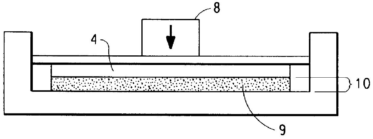
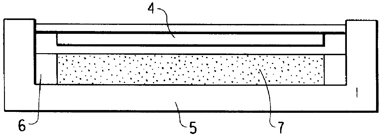
Sintering tests were conducted on each of these materials at various temperatures using a 12 in. diameter press mold of design shown in FIG. 2. The stop depth selected was 0.062 in. for a total mold depth of 0.125 in., al...

example 2

Several mixtures of plastic powders were processed using the procedure outlined in Example 1. A sintering temperature of 200.degree. C. was employed. Mixtures tested are listed in Table 2 below.

TABLE 2 ______________________________________ Powder mixtures used in sintering tests Component 1 Component 2 Component 3 ______________________________________ Texin 470D 50% Isoplast 302 50% Texin 470D 20% Isoplast 302 80% Texin 470D 80% nylon 66 20% Texin 470D 50% Texin 970D 50% Texin 470D 33.33% Isoplast 302 33.33% nylon 66 33.33% ______________________________________

All sintered products showed good flexibility, strength, dimensional precision and porosity, fully equivalent to the best single material samples of Example 1.

example 3

Another top mold plate was prepared which had a series of concentric projecting rings on its inner surface. Pitch spacing was 0.030 in, with a projecting depth of 0.015 in. and a projection width of 0.013 in. This top plate was substituted for the original top plate and used to sinter samples of 970D powder using optimal conditions identified in Example 1. The resulting product had a top surface which had a pattern of concentric circular grooves of a precise mirror image of the projecting concentric circular grooves of the mold surface. Dimensions and dimensional precision were found to be equivalent to the mold, as in the other examples. All portions of the product, including the regions between grooves on the top surface were of uniform porosity.


PUM

PropertyMeasurementUnit
pressureaaaaaaaaaa
mean particle diameteraaaaaaaaaa

Abstract

Polymer-based pads useful for polishing objects, particularly integrated circuits, having interconnected porosity which is uniform in all directions, and where the solid portion of said pad consists of a uniform continuously interconnected polymer material of greater than 50% of the gross volume of the article, are produced directly to final shape and dimension by pressure sintering powder compacts of thermoplastic polymer at a temperature above the glass transition temperature but not exceeding the melting point of the polymer and at a pressure in excess of 100 psi in a mold having the desired final pad dimensions. In a preferred version, a mixture of two polymer powders is used, where one polymer has a lower melting point than the other. When pressure sintered at a temperature not to exceed the melting point of the lower melting powder, the increased stiffness afforded by incorporation of the higher melting polymer component gives improved mechanical strength to the sintered product. Conditions for producing the pads of this invention are such that the polymer powder particles from which the pads are produced essentially retain their original shape and are point bonded to form the pad.

Description

BACKGROUND OF THE INVENTION1. Field of the InventionThe present invention relates to an article of manufacture which is extremely useful as a component used in the polishing of materials, particularly semiconductor crystals and integrated circuits based on silicon wafers. In polishing, the material to be polished (the workpiece) is attached to a flat cylindrical carrier and pressed against a rotating table upon which is attached a polishing pad, generally a sheet of polymeric material. An aqueous suspension of fine particles (the slurry) is poured onto the polishing pad so as to wet the contacting surfaces. The slurry-lubricated friction between workpiece and pad results in the wearing away of surface asperities on the workpiece and the production of a smooth, featureless polished workpiece surface.For many polishing processes, particularly those operating at high rotational speeds or pressures, inadequate slurry flow across the pad / workpiece boundary gives rise to non-uniform polis...

Claims


Application Information

Patent Timeline
Patent Type & Authority Patents(United States)
IPC IPC(8): B24D3/20B24D3/28B24D3/26B24D18/00B24B37/04B24D13/14B24D13/00B29C43/00
CPCB24B37/042B24B37/24B24D3/26B24D3/28B24D18/0009B29C43/006
Inventor COOK, LEE MELBOURNEJAMES, DAVID B.JENKINS, CHARLES WILLIAMREINHARDT, HEINZ F.ROBERTS, JOHN V. H.PILLAI, RAJ RAGHAV
Owner ROHM & HAAS ELECTRONICS MATERIALS CMP HLDG INC
Why Eureka
Try Eureka