Method and device for controlling fast periodic motion

a technology of periodic motion and control device, which is applied in the direction of counting objects on conveyors, optical radiation measurement, instruments, etc., can solve the problems of interpreting data, data acquisition (width of sensing intervals) is accordingly irregular, and limit in real-time analysis, so as to improve the accuracy of measurement and control, the effect of improving the frequency of motion

Inactive Publication Date: 2000-03-21
ESS TECH INT INC
View PDF8 Cites 25 Cited by
  • Summary
  • Abstract
  • Description
  • Claims
  • Application Information

AI Technical Summary

Benefits of technology

is to define an improved method of moving an object, more particularly for controlling periodic motion of a reflector element, which obviates the limitations of conventional procedures and more particularly enables enhanced motion frequency, accuracy, long-term stability and phase stability to be achieved. It is furthermore an object of the invention to define an improved method of establishing an optimum command function for controlling motion of an object. It is also an object of the invention to provide devices for implementing the methods.

Problems solved by technology

However, due to the roughly 0.5 to 2 ms transient phase of the mirrors in abrupt deflection scanning rates of only approximately 500 Hz are achieved, representing a limitation in real-time analysis.
Data acquisition (width of the sensing intervals) is accordingly irregular which is a drawback in interpreting the data.
This, however, has the drawback that only a fraction (e.g. 30%) of the working cycle of a full deflection period is available for data acquisition.
In addition, complicated means of correction may be necessary after data acquisition to linearize the acquired image (see Tsien et al. in "Handbook of Biological Confocal Microscopy", Plenum Press, New York 1995, pages 459-478).
Freely oscillating mirrors have further the disadvantage of low long-term stability.
In addition to the cited problems it is a drawback of the resonance systems that operation is tied to a fixed resonant frequency which as a mechanical parameter cannot be varied and which may result in undesirable beat frequencies when superimposed by other resonant frequencies of the system.
Another problem associated with LSM mirror control is achieving sufficient phase stability when changing the direction of the motion, this being the reason why in conventional LSM in avoiding a dislocation between subsequently scanning lines half of the working cycles are dumped and only the scan for mirror motion in a predetermined direction made use of in each case for data acquisition.
Thus, the problem quite generally in LSM systems is that where mirror control involves feedback with a linear command function the operating frequency is limited and where done without feedback, although higher frequencies can be attained, this is only possible with reduced stability and at the expense of more time and processing being needed.
This problem illustrated by way of LSM systems occurs in all applications in which fast periodic motion of an object having an inert mass needs to be moved in keeping with a command function.
However, this is possible only to a limited extent since self-excited oscillations may occur in the control circuit or the amplifier may be driven into a non-linear operating range.
In both cases prohibitive disturbances materialize for the controlled periodic motion, e.g. of reflector elements, due to undesirable frequency components, this in turn resulting in a restriction to low operating frequencies.

Method used


Image

  • Method and device for controlling fast periodic motion
  • Method and device for controlling fast periodic motion
  • Method and device for controlling fast periodic motion

Examples


Embodiment Construction

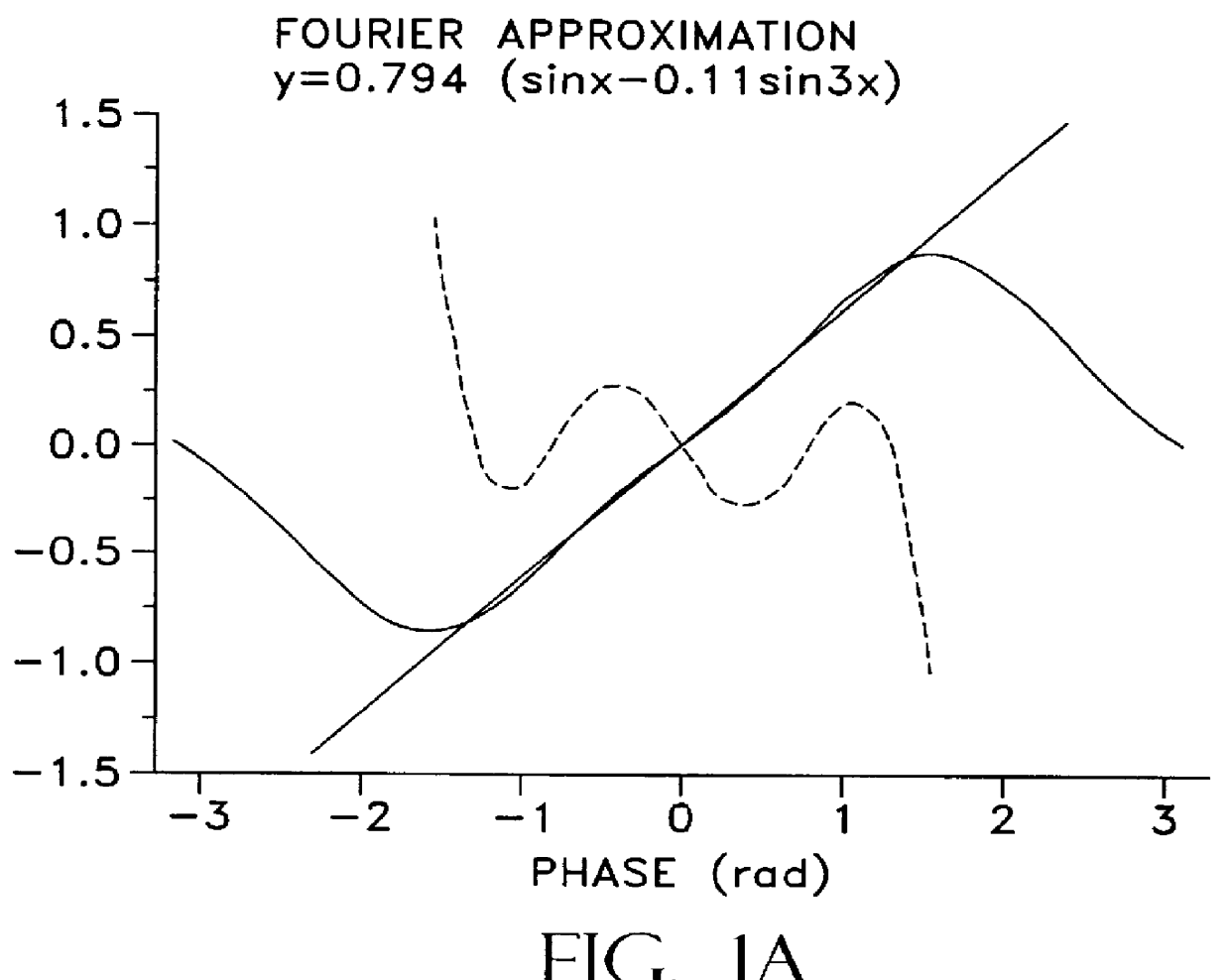
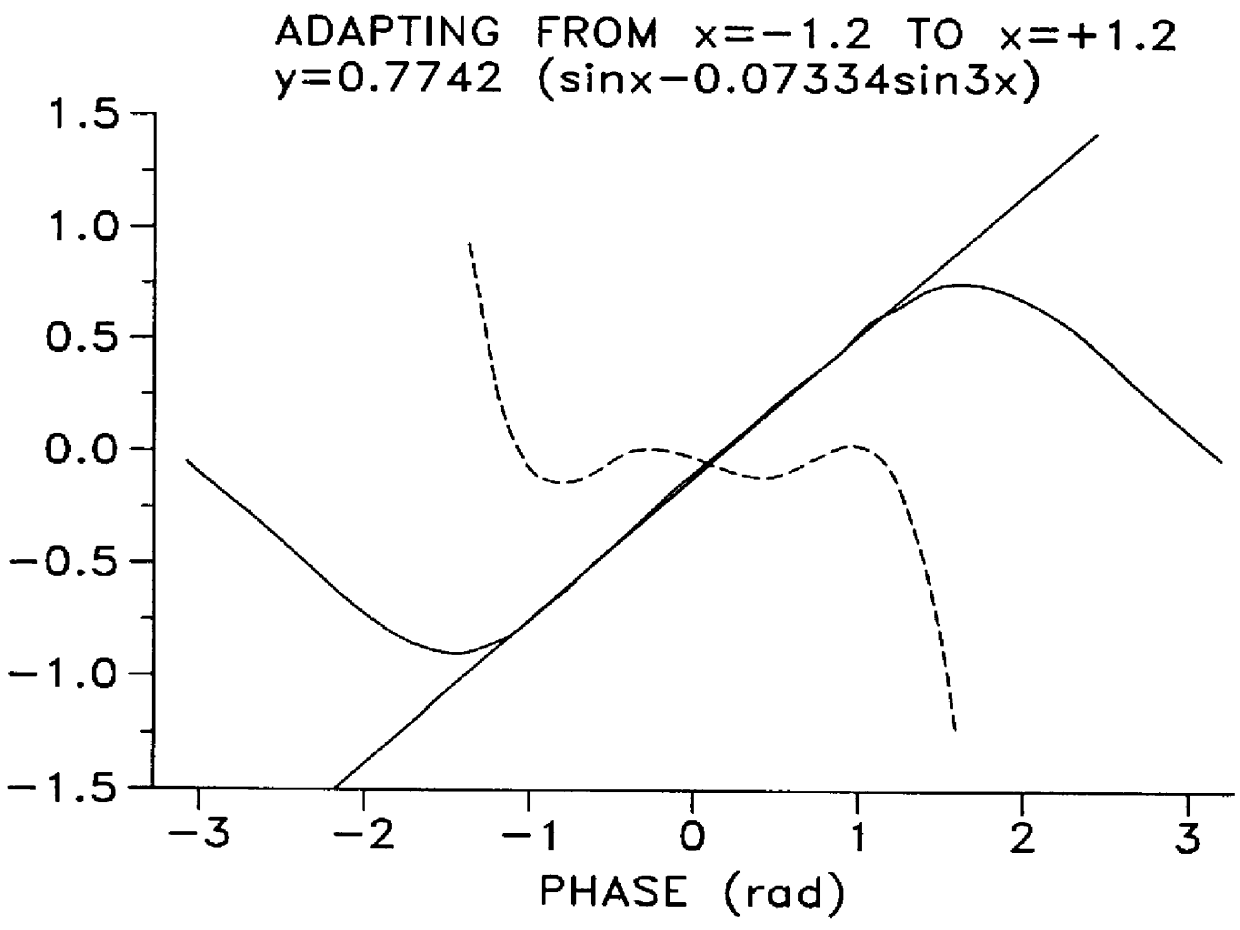
The invention will now be discussed by way of signalling a galvanometer mirror in a LSM as an example. The ideal aim function for deflecting the mirror would be a delta or ramp function (so-called sawtooth function). The advantages of the delta function as compared to the ramp function are as follows: due to the inertia of the mirror and the upper limits of the permissible driver currents the maximum angular acceleration of the mirror is limited, this affecting the ramp function more strongly than the delta function. In addition, in the case of the delta function, both half-cycles of the cycle can be made use of so that higher line frequencies can be anticipated. The following discussion relates to delta functions, whereby solutions materialize correspondingly for ramp functions (see below).

The consideration in the following is a periodic (repetetive) deflection of a galvanometer mirror having a fundamental frequency f.sub.0. After an initial transient phase the deflection can be re...


PUM


Abstract

A method for moving an object such that a location coordinate of the object is adapted at least in one periodic sub-interval to a aim function y<<(t) comprises parameterizing the aim function as a series expansion in accordance with determining n command parameters a1, a2, . . . an, for which an optimization criterion is satisfied in the periodic sub-interval for a command function and signalling the object such that the location coordinate thereof corresponds to the command function. In a closed loop method for setting a controlled variable for a driver function of an engine with amplitude attenuating and phase delay the driver function is formed with amplitude / phase compensation parameters.

Description

1. Field of the InventionThe invention relates to a method for moving or driving an object, more particularly for controlling periodic motion of a reflector element such as e.g. a galvanometer mirror for incremental or "raster"-type deflection of a laser scanning beam, and to devices for implementing the methods.2. Description of the Prior ArtIn measuring and experimenting systems there is often the requirement to raster-scan a system being investigated (sample) as regards a specific quantity to be measured. In a microscope, for instance, a sample is to be scanned by a light signal by means of a movable deflection mirror. The deflection of the deflection mirror is required to obey a specific time pattern to which data acquisition is adapted. Another example is the scanning motion of field-forming elements (e.g. grids) for local resolving electron-spectroscopic analyzers.The problems associated with signal control in generating scanning motion will now be discussed by way of a deflec...

Claims


Application Information

Patent Timeline
Patent Type & Authority Patents(United States)
IPC IPC(8): G02B26/10
CPCG02B26/105
Inventor NEHER, ERWINWURRIEHAUSEN, FRANK
Owner ESS TECH INT INC
Why Eureka
Try Eureka