
Vertical passive components for surface mount assembly

a technology of vertical passive components and assembly, which is applied in the direction of manufacturing tools, fixed capacitor details, printed circuit non-printed electric components association, etc., can solve the problems of major mismatch affecting signal integrity on the line, affecting the integrity of signal integrity of lines, and affecting the use of power supplies

Inactive Publication Date: 2000-03-21
TEXAS INSTR INC
View PDF6 Cites 40 Cited by
  • Summary
  • Abstract
  • Description
  • Claims
  • Application Information

AI Technical Summary

Problems solved by technology

As circuits get more complex the number of power supplies increase and so the need for capacitors.
Connecting them directly would result in a major mismatch which will affect signal integrity on the line.
In particular, de-coupling capacitors are a problem since each memory integrated circuit needs at least one.
Also, resistors used in the input and outputs of memory devices are becoming more of a problem since memories are offered in a variety of configurations such as X1, X4, X8, X16, X32 and X64.
The shape, size and orientation of the present passive electrical components forces the user to mount them adjacent to the active devices which waste a great deal of space on the assembly.

Method used


Image

  • Vertical passive components for surface mount assembly
  • Vertical passive components for surface mount assembly
  • Vertical passive components for surface mount assembly

Examples


Embodiment Construction

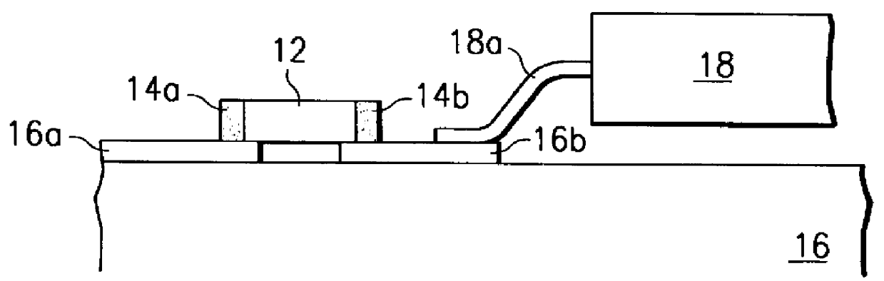
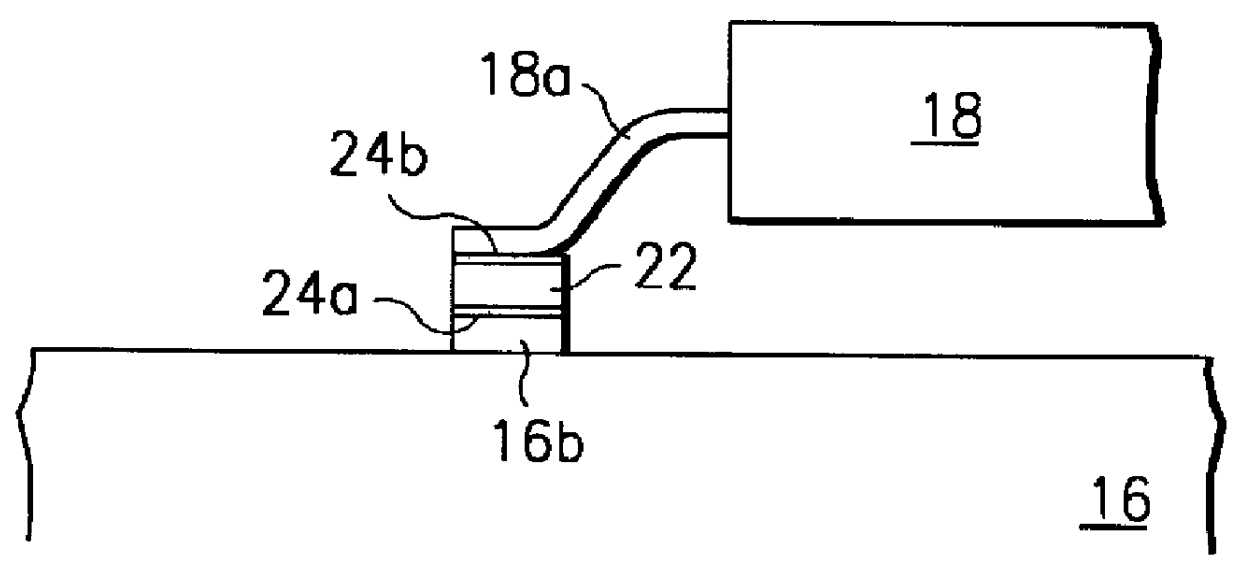
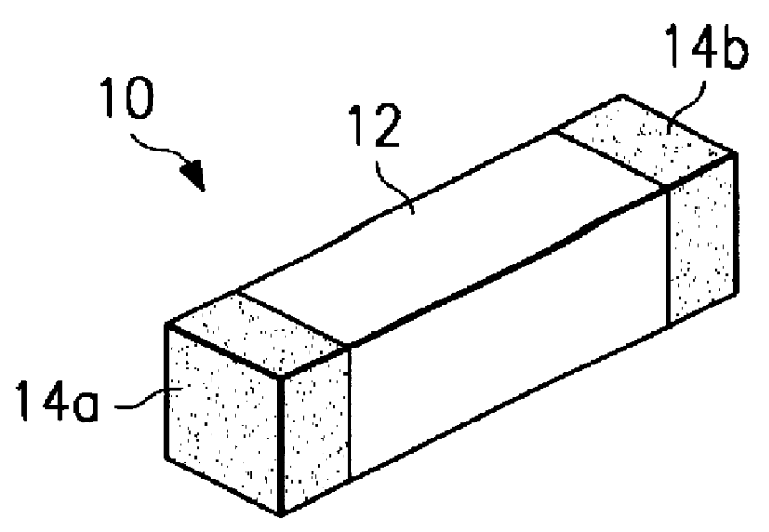
FIG. 3 is a drawing illustrating a passive electrical component 20 according to the preferred embodiment of the invention. The component 20 may be, for example, a resistor, capacitor or inductor. It has a body 22 with metallic terminations 24a and 24b on each end. However, unlike prior art component 10 of FIG. 1 which is configured for horizontal attachment to a PWB, the inventive component 20 is configured for vertical attachment to a PWB. Terminations 24a and 24b are on the upper and lower sides of body 22 and may be comprised of a solder material. The component 20 is approximately the size of the soldering pad for the active component and can be in horizontal section round, square, rectangular or any other shape approximating the shape of the soldering pad and lead. The thickness of component 20 is relatively small, and may be (for example) up to about 30 to 40 mills thick. It should be about the same or smaller in width than the size of a lead finger and may extend outside the l...


PUM


Abstract

In a surface mount assembly, an active integrated circuit device, such as, for example, a dynamic random access memory, typically has a lead finger attached to a solder pad of a printed wiring board. The surface mount assembly is significantly improved by configuring a passive component, such as a resistor or capacitor, such that it has metallic terminations on an upper and lower surface so that it may be positioned between the solder pad of the printed wiring board and the lead finger.

Description

This invention relates generally to the field of electrical components and more specifically to passive electrical devices mounted on printed wiring boards.As the semiconductor industry moves towards higher circuit densities and larger memory sizes (such as 64 megabit dynamic random access memories "DRAMs" and 256 megabit DRAMs) more stringent requirements are being placed on low frequency noise suppression (also known as power line de-coupling) and noise filtering systems on printed wiring boards (PWBs), or printed circuit boards. De-coupling, or bypass, capacitors are necessary to provide a temporary supply of charge to the active integrated circuits as the output of power supplies connected to the integrated circuits varies. In this way, circuit operation is not compromised due to a temporary drop in voltage supply. De-coupling capacitors are typically in the 0.5 to 1 microfarad range. They are located between the power supplies and the ground. The trace on the board can be at th...

Claims


Application Information

Patent Timeline
IPC IPC(8): H05K1/02H01G4/232
CPCH01G4/232H05K1/023H05K1/0231H05K2201/10022H05K2201/10515H05K2201/1053H05K2201/10643H05K2201/10689
Inventor BAUDOUIN, DANIELRUSSELL, ERNEST J.JANZEN, JEFFREY W.
Owner TEXAS INSTR INC
Features
  • Generate Ideas
  • Intellectual Property
  • Life Sciences
  • Materials
  • Tech Scout
  • Unparalleled Data Quality
  • Higher Quality Content
  • 60% Fewer Hallucinations
Learn More