Cathode for electronic tube

a cathode and electronic tube technology, applied in the direction of discharge tube/lamp details, discharge tube main electrodes, discharge tube solid thermionic cathodes, etc., can solve the problems of large fluctuation of hue, large brightness of screen, and large deviation of cutoff voltage, and achieve high brightness and resolution.

Inactive Publication Date: 2000-04-25
THOMSON LICENSING SA
View PDF1 Cites 2 Cited by
  • Summary
  • Abstract
  • Description
  • Claims
  • Application Information

AI Technical Summary

Benefits of technology

Accordingly, the heat deformation is made extremely small and drift of cutoff voltage is suppressed because the thickness of the metal layer is 0.01 to 1.5 .mu.m and the metal layer contains 0.001 to 0.5% by weight of the same metals as those contained in the substrate, thereby enabling the substrate to be used in cathode ray tubes with high brightness and high resolution.

Problems solved by technology

A problem arose due to this deformation in that the distance between the first grid (electrode) and the surface of the cathode fluctuates, resulting in a drift of the cutoff voltage.
This drift in the cutoff voltage also caused a problem in that after a prolonged operating time, the brightness of the screen greatly fluctuates or, in the case of color cathode ray tubes, the hue is greatly fluctuates.

Method used


Image

  • Cathode for electronic tube
  • Cathode for electronic tube
  • Cathode for electronic tube

Examples


example 2

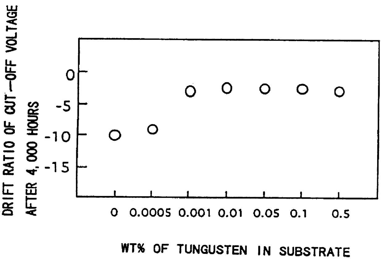
FIG. 4 shows the relationship between the drift ratio of cutoff voltage of a CRT after 4000 operating hours and the ratio of the weight of the metal in the substrate to the weight of the metal layer on the substrate completed via a conventional evacuation means after equipping a conventional television with the cathode for electronic tubes according to the present invention.

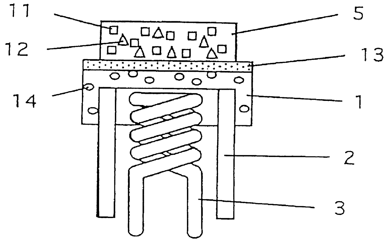
The metal layer 13 as used herein was subjected to heat treatment at 1000.degree. C. in a hydrogen atmosphere after forming a tungsten film with a thickness of 0.01 .mu.m. Alkali earth metal oxides containing 7% by weight of scandium oxide was used as the electron emitting material 5. The content of the metal 14 in the substrate 1 may be determined from the ratio of the weight of the substrate to the weight of the metal layer. Tungsten is used as the metal 14, and is contained in the substrate in a ratio of the weight of the metal 14 to the weight of the metal layer 13 of 0 to 150. As indicated in FIG. 4, it was ...


PUM

PropertyMeasurementUnit
thicknessaaaaaaaaaa
thicknessaaaaaaaaaa
thicknessaaaaaaaaaa

Abstract

PCT No. PCT/JP97/01976 Sec. 371 Date Feb. 20, 1998 Sec. 102(e) Date Feb. 20, 1998 PCT Filed Jun. 10, 1997 PCT Pub. No. WO97/49108 PCT Pub. Date Dec. 24, 1997Problems with a conventional cathode for electronic tubes arose because metals composing the substrate were subjected to heat deformation, resulting in a relatively lage drift of cutoff voltage. The present invention diminishes the heat deformation of the substrate to obtain a cathode with a small drift of cutoff voltage. Particularly, heat expansion coefficients can be made uniform while metals in the metal layer are prevented from diffusing into the substrate. This is done by incorporating the same metals present in the metal layer into the metals composing the substrate, thereby supressing deformation of the substrate.

Description

This invention relates to a method for improving the performance of an electronic tube, more specifically to a method for suppressing drift of cut-off voltage during operation.FIG. 6 shows a conventional cathode for an electronic tube used in cathode ray tubes in televisions and image pickup tubes as disclosed in Japanese Patent Laid-open No. 3-257735.In FIG. 6, 1 is a substrate mainly composed of nickel (Ni) containing a small amount of reduction elements such as silicon (Si) and magnesium (Mg), 2 is a cathode sleeve composed of chromium and the like, 13 is a metal layer mainly composed of at least one or more of tungsten, molybdenum, tantalum, chromium, silicon and magnesium, and 5 is a layer of an electron-emitting material deposited on the metal layer 13, containing at least barium in addition to alkali earth metal oxides 11 which include strontium and / or calcium as main components and also containing 0.1 to 20% by weight of rare earth metal oxides 12 such as scandium oxide, and...

Claims


Application Information

Patent Timeline
Patent Type & Authority Patents(United States)
IPC IPC(8): H01J1/20H01J1/26H01J1/142H01J1/13
CPCH01J1/26H01J1/142
Inventor OHIRA, TAKUYASAITO, MASATOTERAMOTO, HIROYUKI
Owner THOMSON LICENSING SA
Why Eureka
Try Eureka