Heater equipped spark plug

a technology of spark plugs and heat exchangers, applied in spark plugs, spark plugs, spark plug manufacture, etc., can solve the problems of short service life, easy failure of electrical insulation, and inconvenient us

Inactive Publication Date: 2000-05-09
NGK SPARK PLUG CO LTD
View PDF12 Cites 32 Cited by
  • Summary
  • Abstract
  • Description
  • Claims
  • Application Information

AI Technical Summary

Benefits of technology

Owing to the construction described above, the heater which has been formed by baking the metal paste is disposed on the insulator nose, which holds the center electrode in the vicinity of the free end of the axial bore, and is connected to the lead wire arranged along a surface of the insulator. Further, the heater is covered with the high softening-point glass and, preferably, the thickness of the covering layer of the high softening-point glass can range from 30 .mu.m to 500 .mu.m. This has made it possible to ensure sufficient voltage withstand performance, to prevent deposit of carbon on the insulator nose by heating the insulator nose with the heater while protecting the heater from damages by thermal shocks, and also to sufficiently prevent production of a spark between the center electrode and the heater arranged on the insulator nose owing to excellent electrical insulating properties of the high softening-point glass.
Further, as the heater arranged on the insulator nose is covered and held in place by the high softening-point glass with the alumina layer interposed therebetween, the alumina layer can prevent cut-off of the heater, which would otherwise occur as a result of a change in the resistance value of the heater under the migration effect that the metal component (Si) contained in the high softening-point glass is caused to melt out when silicon oxide (SiO.sub.2) abundantly contained in the high softening-point glass is heated to a high temperature upon feeding of a current to the heater and is maintained in the heated state. By setting within 20-200 .mu.m the thickness of the alumina layer held between the heater and the high softening-point glass, it is possible not only to prevent cut-off of the heater, which would otherwise occur under the migration effect, but also to improve the impact resistance of the alumina layer itself.
In addition, the heater and the alumina layer can be provided in a form integrally bonded with the insulator nose by forming, for example, printing on a resin sheet a heater-forming layer and an alumina paste layer with a metal paste and an alumina paste, adhering the resin sheet on an unsintered green body corresponding to the insulator nose and then simultaneously sintering the heater-forming layer and the alumina paste layer together with an unsintered green body corresponding to the insulator and including the first-mentioned unsintered green body. This fabrication process can improve the productivity of the heater-equipped spark plug according to the present invention despite its rather complex structure. Further, the arrangement of the heater in the recess can prevent the glass from flowing out so that the positioning of the heater can be facilitated.

Problems solved by technology

Because the nichrome wire is prone to oxidation and burning-up through its exposure to high-temperature combustion gas of a gas-fuel mixture, the spark plug is accompanied by the drawback that its service life is short.
These conventional spark plugs are however still accompanied by one or another drawback.
It is simple in structure but, as it is provided with almost no electrical insulation or only with incomplete electrical insulation for the protection of the heater itself, the electrical insulation easily fails during an operation of an internal combustion engine and a spark is hence produced between an associated center electrode and the resistance heating pattern formed from the high m.p. metallized ink and buried in the surface of the insulator nose.
The spark plug therefore involves the drawback that the ignition of an air-fuel mixture may become insufficient.
The insulating covering layer, which was made from the ceramic sheet or paste of alumina or the like and covers the resistance heating pattern printed on the ceramic substrate, is however susceptible to breakage due to increased combustion gas pressure produced in an associated combustion chamber as a result of the recent move toward high-performance internal combustion engines.
The insulating covering layer can no longer maintain sufficient electrical insulation, leading likewise to the drawback that no full ignitability can be retained for an air-fuel mixture.

Method used


Image

  • Heater equipped spark plug
  • Heater equipped spark plug
  • Heater equipped spark plug

Examples


first embodiment

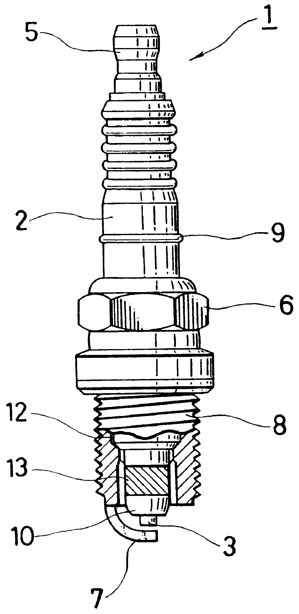
the present invention will now be described with reference to FIG. 1 and FIG. 2.

Referring first to FIG. 1, numeral 1 designates the heater-equipped spark plug according to the first embodiment of the present invention. This heater-equipped spark plug 1 is composed of an insulator 2, a center electrode 3 projecting from one end of the insulator 2, a terminal electrode 5 provided at an opposite end of the insulator 2 with a basal portion thereof fixedly sealed or otherwise held within an axial bore of the insulator 2, and a metal shell 6 having a ground electrode 7 at a free end thereof, that is, at a position opposite to a free end of the center electrode 3 and a threaded portion 8 adapted to threadedly fix the spark plug 1 in a plug hole upon mounting the spark plug 1 on an internal combustion engine.

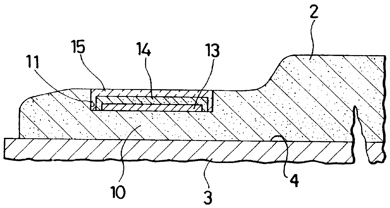
Reference is next had to FIG. 2. A recess 11 is formed in an insulator nose 10 of the insulator 2. This insulator nose 10 holds thereon the center electrode 3 in the vicinity of a free ...


PUM


Abstract

A heater-equipped spark plug comprises an insulator having an insulator nose which holds thereon a center electrode in the vicinity of a free end of an axial bore, a lead wire arranged along a surface of the insulator, a heater formed on the insulator nose by baking a metal paste and connected to the lead wire; and a high softening-point glass layer covering and holding the heater in place with an alumina layer interposed between the high softening-point glass and the heater. Preferably, the alumina layer can have a thickness of 20-200 mu m and the high softening-point glass layer can have a thickness of 30-500 mu m.

Description

a) Field of the InventionThis invention relates to the structure of a spark plug, which is suitable for use in an internal combustion engine of an automotive vehicle or the like and has improved anti-fouling properties against the deposit of carbon on an insulator nose, especially at low temperatures.b) Description of the Related ArtTo prevent deposit of carbon on an insulator nose, especially at low temperatures when employed in an internal combustion engine of an automotive vehicle or the like, it has heretofore been the general practice to use a spark plug with a nichrome wire wound on and around an insulator nose which holds a center electrode in the vicinity of a free end of an axial bore. Because the nichrome wire is prone to oxidation and burning-up through its exposure to high-temperature combustion gas of a gas-fuel mixture, the spark plug is accompanied by the drawback that its service life is short. With a view to overcoming this drawback, spark plugs have been proposed, ...

Claims


Application Information

Patent Timeline
Patent Type & Authority Patents(United States)
IPC IPC(8): H01T21/02H01T13/18H01T13/00H01T21/00H01T13/20
CPCH01T21/02H01T13/18
Inventor SUZUKI, TAKAHIROITO, YUKIHIKO
Owner NGK SPARK PLUG CO LTD
Why Eureka
Try Eureka