Device and method for recommending dynamically preferred speeds for machining

a dynamically preferred, machine technology, applied in the direction of metal-working machine components, instruments, manufacturing tools, etc., can solve the problems of reducing the quality of the machined surface, limiting the productivity of the machining process, and limiting the speed of machining, so as to achieve stable machining

Inactive Publication Date: 2000-07-04
BLUESWARF
View PDF38 Cites 59 Cited by
  • Summary
  • Abstract
  • Description
  • Claims
  • Application Information

AI Technical Summary

Benefits of technology

to provide a simplified means of measuring machining process behavior and establishing rotational speed recommendations which are likely to result in more stable machining.

Problems solved by technology

Machining processes such as turning, boring, milling and drilling are often limited by undesirable vibration in the form of chatter.
The chatter is a result of an unstable machining process caused by the relative vibratory motion between the cutting tool and workpiece.
This common problem in industry reduces the quality of the machined surface, limits the productivity of the machining process and often reduces the life of the cutting teeth or results in tool failure.
In these ways the stability of the machining process is increased by design, although the continuous drive for greater productivity and manufacturing flexibility inevitably pushes many machining operations to chatter.
The efforts of most of these techniques have been unsatisfactory for a variety of reasons, including limited application to specific machining operations, conditions or tooling; modification of machinery controls and drives; numerous sensor types and integration; extensive prior knowledge required of the dynamic characteristics of the machine tool, workpiece or process program and machining limits.
Such an arrangement is fairly complex and may require altering the software of a preprogrammed machine tool controller.

Method used


Image

  • Device and method for recommending dynamically preferred speeds for machining
  • Device and method for recommending dynamically preferred speeds for machining
  • Device and method for recommending dynamically preferred speeds for machining

Examples


Embodiment Construction

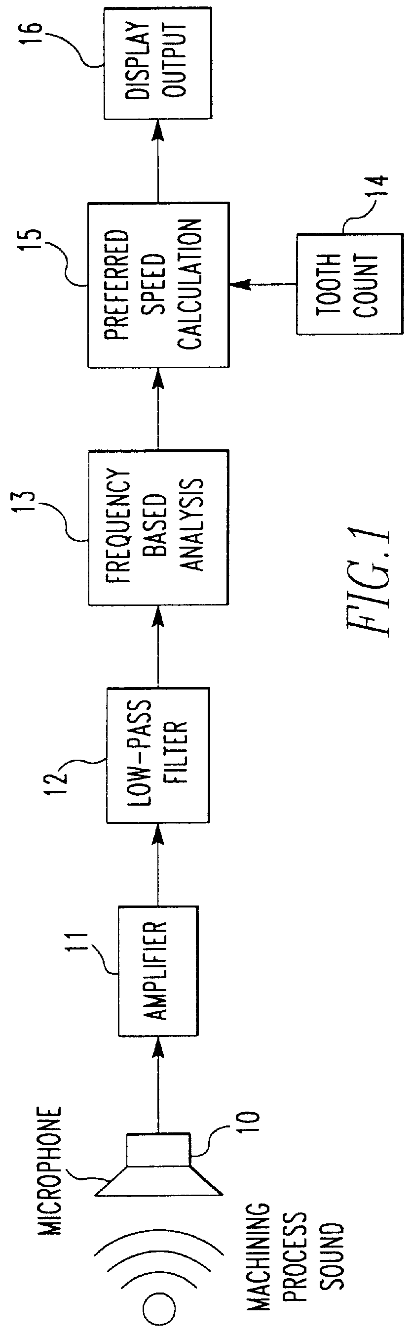
Referring to FIG. 1, the functional flow of the present invention is depicted. A single audio sensor comprising a microphone 10 capable of detecting sound pressure emanating from the machining process produces a raw data signal. A stepped gain amplifier 11 and low pass filter 12 condition the signal to provide enhanced signal-to-noise characteristics and avoid aliasing if a digital representation of the signal is employed. The signal frequency component with the greatest magnitude is established from a frequency based analysis 13. The dominant frequency may be determined using analog approaches, including but not limited to a frequency counter, frequency-to-voltage converter or moving filter techniques. The conditioned signal may be digitally represented and digital signal processing techniques such as fast Fourier, fast Hartley or other transforms which yield coefficients indicating spectral components may be employed. Based on the identified frequency of the dominant signal compon...


PUM


Abstract

A hand-held, portable device recommends dynamically preferred speeds for stabilizing or reducing undesirable vibration such as chatter in a machining process. The device may be applied to machining processes such as turning, boring, milling and drilling which exhibit a relative rotational motion between the cutting tool and workpiece. The device measures in a safe, non-contact manner via a microphone the dominant audio signal component of the sound pressure emanating from the machining processes. Without prior knowledge of the machining process parameters or the dynamic characteristics of the machine tool or workpiece, the audio signal is conditioned and processed to determine the frequency component levels. The rotational speeds which are more likely to lead to a stable machining process are calculated based on the number of teeth on the cutting tool and the identified dominant frequency of vibration. The dynamically preferred speeds are displayed as recommendations to the process operator or machinist.

Description

1. Field of the InventionThis invention relates to an electronic device which measures sound emanating from a machining process and displays preferred rotational speed recommendations to eliminate or reduce undesirable vibration known as chatter. More particularly, the device is applicable to machining operations which exhibit a relative rotation between a tool having one or more cutting teeth and a workpiece. This device provides a safe means for the operator to interactively measure and determine the recommended speeds without prior knowledge or modification of the machine tool and workpiece.2. Description of the Prior ArtMachining processes such as turning, boring, milling and drilling are often limited by undesirable vibration in the form of chatter. The chatter is a result of an unstable machining process caused by the relative vibratory motion between the cutting tool and workpiece. This common problem in industry reduces the quality of the machined surface, limits the product...

Claims


Application Information

Patent Timeline
Patent Type & Authority Patents(United States)
IPC IPC(8): B23Q17/12B23Q15/08B23Q17/09
CPCB23Q17/0976B23Q17/12B23Q17/098
Inventor STERN, ELLIOT L.
Owner BLUESWARF
Why Eureka
Try Eureka