Near net-shape VPS formed multilayered combustion system components and method of forming the same

Inactive Publication Date: 2000-07-11
PYROGENESIS
View PDF11 Cites 10 Cited by
  • Summary
  • Abstract
  • Description
  • Claims
  • Application Information

AI Technical Summary

Benefits of technology

It should further be mentioned that when re-usable molds are employed, one of the important and novel features of the present invention is the embodiment providing for deposition of the debonding layer onto the mold. It has been found that without such debonding layer, it is difficult to separate the final component from the mold. Thus, the applicants have developed a novel procedure whereby a debonding layer is first vacuum plasma sprayed onto the mold, which significantly improves subsequent separation of the mold from the multilayered component. Such debonding layer plays two somewhat contrasting roles. One role is that this debonding layer should be sufficiently strong to provide enough adhesion between the mold and the top coat to allow for the build-up of the entire multilayered component, whereas the second role is that this debonding layer should be weak enough for allowing detachment or debonding of the mold from the final component upon subsequent cooling of the structure. The debonding layer is normally made of the same material as the top coat (or some similar compatible material tha

Problems solved by technology

The transition ducts in particular have a fairly complex geometry and the presently known technology does not allow for satisfactory coating of internal surfaces of components with such complex geometries.
There are several significant problems with components which have been fabricated in this fashion.
One problem is the nonhomogeneity at the welds.
Weld regions act as weak sites from which failure may initiate due to poor quality finish of both the top coat and the bond coat of the TBC.
Also, due to the rough surface of the TBC inherent in the APS process and particularly of the weld regions

Method used


Image

  • Near net-shape VPS formed multilayered combustion system components and method of forming the same
  • Near net-shape VPS formed multilayered combustion system components and method of forming the same
  • Near net-shape VPS formed multilayered combustion system components and method of forming the same

Examples


Embodiment Construction

This example illustrates the fabrication of a combustor liner according to the present invention.

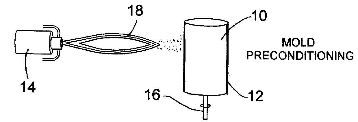
A mold of stainless steel 304 was used for this example. The outer diameter of the mold was machined so as to achieve a near net-shape of the inner diameter of the desired combustor liner, taking into account the mold expansion factor (determined from previous trials). In this case, it was machined so as to achieve a combustor liner of 18 cm internal diameter.

The mold surface was grit blasted and ultrasound cleaned prior to its introduction into the VPS chamber. Upon closing the chamber door, the system was pumped down to 6.times.10.sup.-3 mbar.

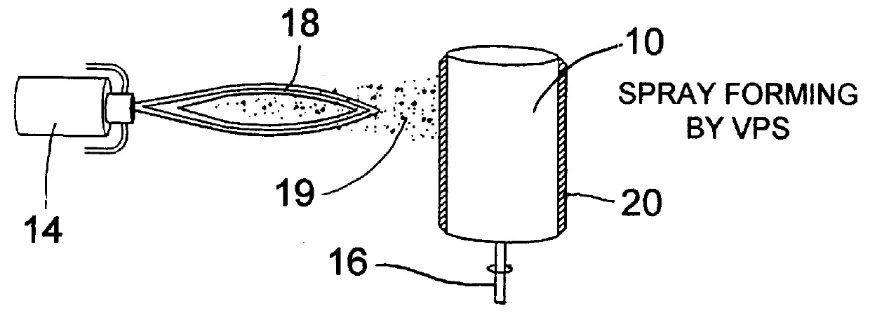
The following procedures were then carried out:

increase chamber pressure to 70 mbar, by introducing argon gas;

spray 4 passes of zirconia (40-60 .mu.m thick) [debonding layer];

shut off powder flow;

decrease pressure to 60 mbar;

heat surface with torch to 620.degree. C.;

increase pressure to 150 mbar;

spray 22 passes of calcia-silica and zirconia combin...


PUM

PropertyMeasurementUnit
Thicknessaaaaaaaaaa
Thicknessaaaaaaaaaa
Thicknessaaaaaaaaaa

Abstract

The invention provides an improved near net-shape VPS formed multilayered combustion system component having an inner surface consisting of a smooth protective thermal barrier coating, and an outer layer of superalloy capable of withstanding temperatures in excess of 700 DEG C. The invention also includes the method of forming such components by first vacuum plasma spraying a suitable mold with a ceramic top coat, followed by a bond coat and followed by a thick structural layer of superalloy. The mold is then separated from the multilayered structure which results in the desired near net-shape component. Combustor liners and transition ducts of gas turbine engines can be advantageously formed in this manner.

Description

1. Field of the InventionThis invention relates to improved multilayered combustion system components, such as combustor liners or transition ducts of a gas turbine engine, wherein the inner surface comprises a protective thermal barrier coating (TBC), which includes a ceramic top coat and a metallic bond coat, and the outer surface consists of a structural layer bonded to the TBC through the bond coat. The improved qualities of the new components over current components include a superior thermal barrier coating, a better high-temperature structural material, a smoother inside surface, no irregularities (welds) within the component, and excellent reproducibility. This is accomplished by a vacuum plasma spray (VPS) process which is used to form the ceramic top coat layer on a suitable mold, followed by a metallic bond coat layer and ending with a structural superalloy layer. Thereafter, the mold is removed to form the multilayered component of the present invention.2. Description of...

Claims


Application Information

Patent Timeline
IPC IPC(8): C23C4/18
CPCC23C4/185Y10S428/937Y10T428/12472Y10T428/12611Y10T428/12618Y10T428/12861Y10T428/12931Y10T428/12736
Inventor TSANTRIZOS, PETER G.KIM, GEORGE E.CAVASIN, ALEXANDER P.GRENIER, SERGE
Owner PYROGENESIS
Why Eureka
Try Eureka