

Segmented abradable ceramic coating
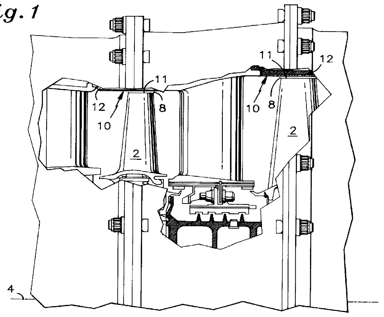
a ceramic coating and segment technology, applied in the field of duct segments, can solve the problems of reducing the useful life of the duct segment 10, affecting the efficiency of the gas turbine engine, and reducing the spallation of the coating, so as to achieve the effect of effective sealing system and prolonging or even increasing the useful life of the duct segment 10
- Summary
- Abstract
- Description
- Claims
- Application Information
AI Technical Summary
Benefits of technology
Problems solved by technology
Method used
Image

Examples
Embodiment Construction
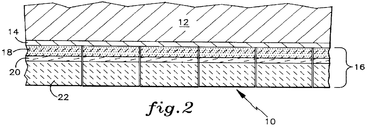
Nickel based high pressure turbine duct segments which were previously coated with a NiCoCrAlY oxidation resistant bondcoat were loaded into a hollow cylindrical fixture having a 30 inch (0.76 m) diameter such that the bond coated surface of the duct segments faced the center of the fixture. The HVOF process previously described was used to apply the NiCoCrAlY bondcoat to the duct segments.
A Sulzer Metco, Inc. 3MB air plasma spray gun was positioned in the interior of the fixture which rotated at about 12 rpm. The gun was located at about a 90 degree angle to the inside surface of each duct segment to be coated in turn. Three distinct layers were created on the bondcoated duct segments using the parameters set forth in Table 1 below. The layers were deposited in one continuous spray process to avoid any potential weak links in the overall coating due to momentarily stopping the process. This continuous process was possible with the use of several Miller Thermal Model 1250 powder fee...
PUM
| Property | Measurement | Unit |
|---|---|---|
| thick | aaaaa | aaaaa |
| thick | aaaaa | aaaaa |
| weight percent | aaaaa | aaaaa |
Abstract
Description
Claims
Application Information