
Molding press apparatus

Inactive Publication Date: 2000-08-22
AEROJET ROCKETDYNE HLDG INC
View PDF27 Cites 20 Cited by
  • Summary
  • Abstract
  • Description
  • Claims
  • Application Information

AI Technical Summary

Benefits of technology

The present application provides a new and improved molding press for molding work pieces using a movable extruder / injection assembly. The use of the present apparatus permits the joining of several work pieces at multiple work stations, at which a single extruder / injection assembly is moved to engage the respective work stations. The use of the injection molding apparatus to join work pieces eliminates the use of potentially hazardous materials near the operator, such as the adhesives which are used in the prior art processes. Additionally, the use of an injection molding process to join work pieces improves product quality due to the superior temperature strength of an injection molded joint, as compared to a joint formed by adhesives. The improved appearance of work pieces joined by injection molding also results in reduced labor due to the reduction of cosmetic or finish work required to be performed on the completed parts.
The movable extruder / injection assembly includes a stock supply portion, an extruder portion, and an injection portion having a nozzle assembly for injecting molding material into the self-actuating mold clamp assembly. Several embodiments of the nozzle assembly of the apparatus are illustrated in the present application. A universal removable check valve is provided in the extruder portion to prevent back flow of injection material to the extruder portion during injection. A spring biased check valve is also provided in the nozzle assembly for preventing nozzle leakage during plasticizing following injection.
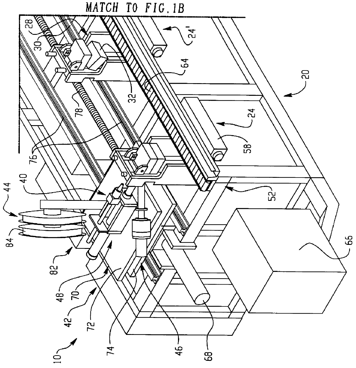
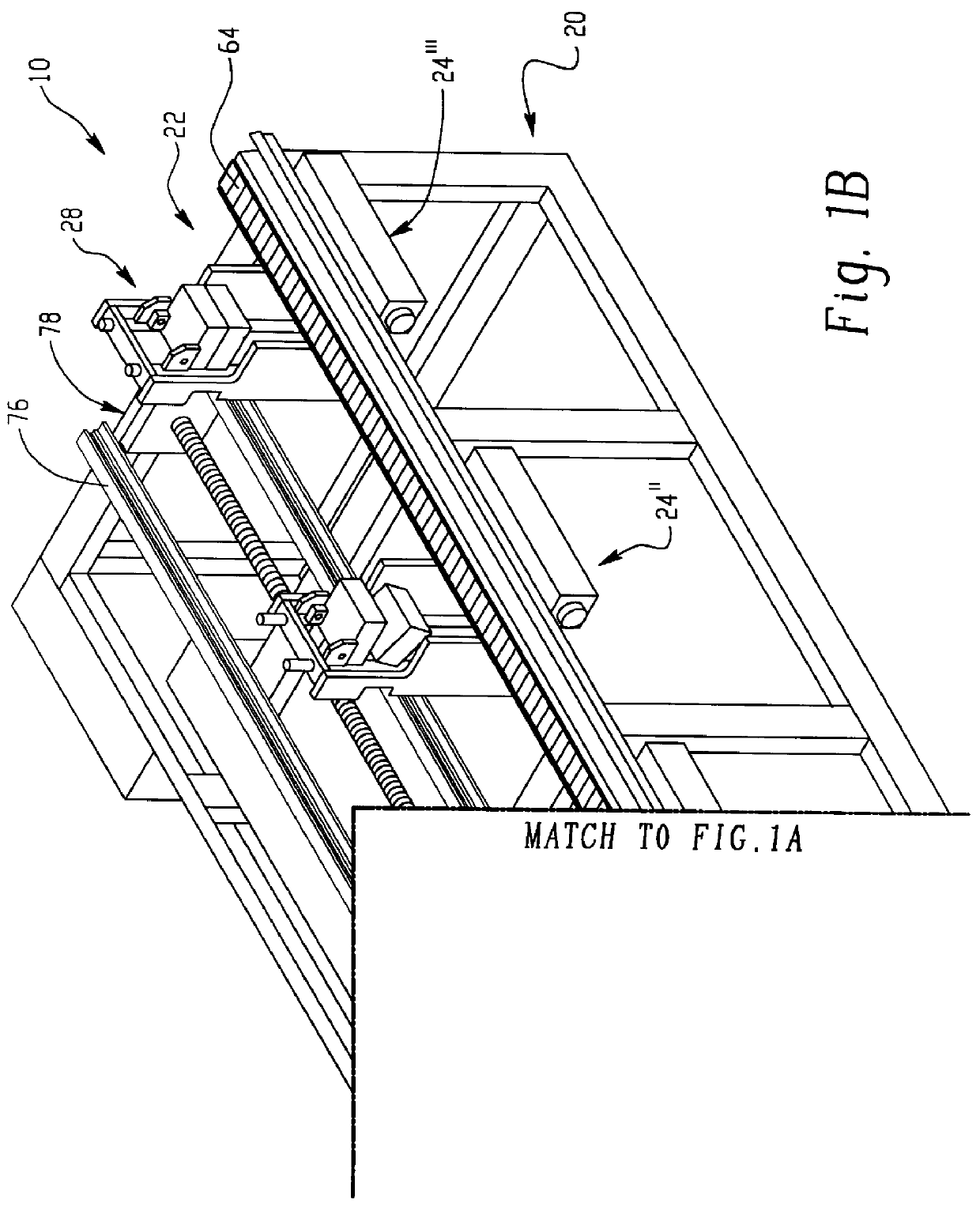
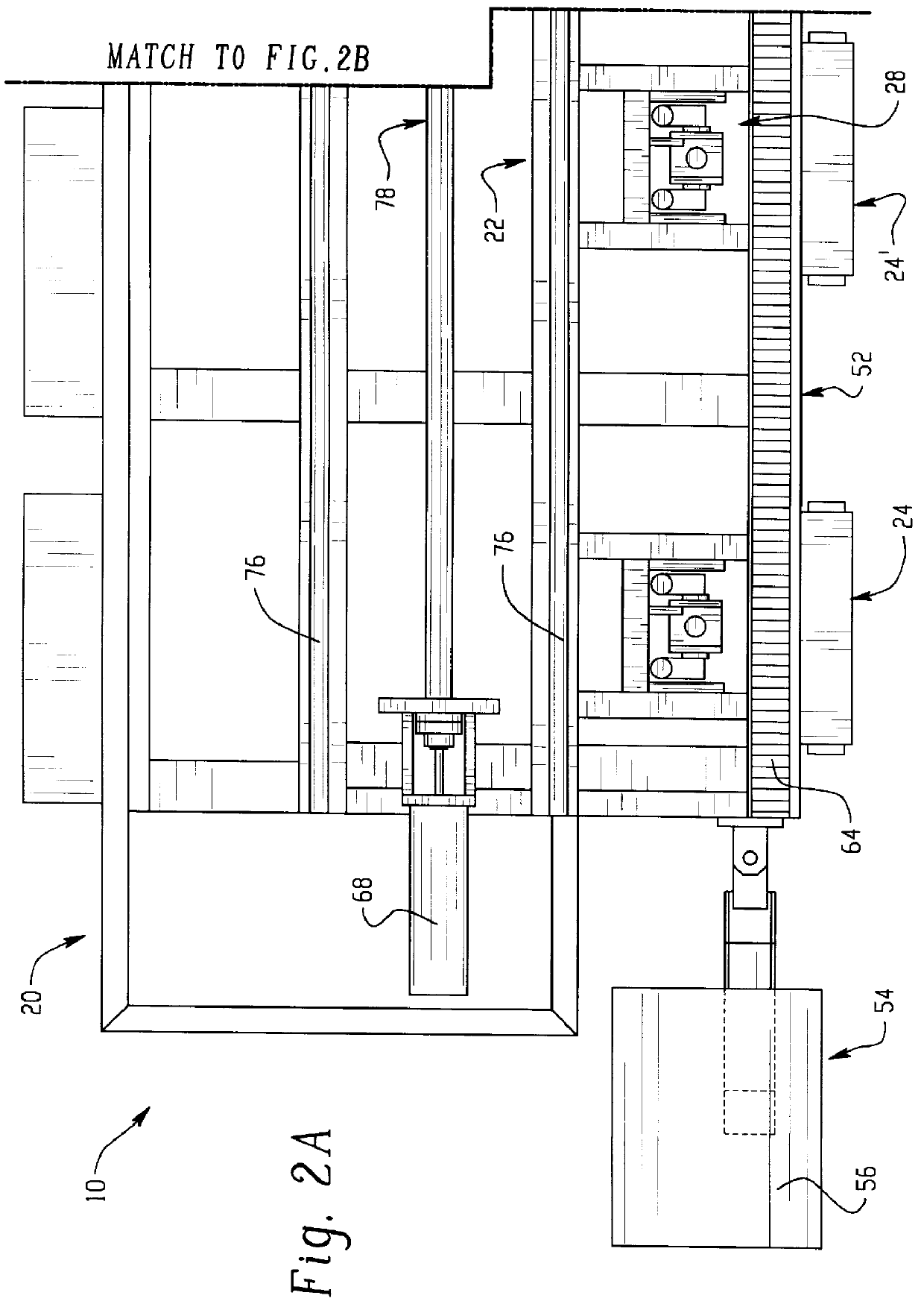
The extruder / injection assembly is moved between the work stations by a shuttle assembly. In the illustrated assembly, injection portion of the extruder / injection assembly is positioned horizontally on the shuttle assembly. However, the use of a vertical injector which would also enable the injection of dual materials is also possible. The use of a single movable extruder / injection assembly reduces the labor costs resulting from multiple handling, conveying and storage of stock or feed supplies which are provided to the extruder portion of the assembly for injection.
In the example of the present apparatus, the molding press apparatus is configured for joining two elongate work pieces of extrudate, and the mounting structure is shaped to match the finished product requirements. As illustrated, the cross-sectional configuration of the mounting structure typically matches that of the work pieces, and may have any overall configuration desired to form the joint between the two work pieces. However, the apparatus may be adapted for many insert molding procedures other than joint molding, such as small part products. The extruder / injection assembly is particularly well adapted to deliver small shot sizes of injection material, such as approximately 25 grams or less, accurately and repeatedly.
In the open position, the operator of the apparatus inserts the work pieces to be molded within the mounting structure prior to the injection operation. The mold plates of the clamping assembly are movable such that either or both of the plates tilts when opened to enable the operator a clear view of, and access to, the work station, as well as reducing the potential for physical injury to the operator in the form of carpel tunnel injury.
Once the work pieces are engaged, the top and bottom mold plates are moved to the closed position, and the nozzle assembly may then be moved into engagement with the sprue opening of the first work station for the injection operation. Once completed, the mold plates are moved to the open position, and may be tipped to enable the ready removal of the molded parts from the clamping assembly by the operator. The tipping of the mold plates assists the operator in insertion and removal of the work pieces, and reduces the potential for physical injury to the operator resulting from the repetitive nature of the insertion and removal tasks.

Problems solved by technology

The use of adhesives for joining such parts has the disadvantage that undesirable fumes or other materials may result from the use of such adhesives.
Also, the use of adhesives at an operator work station typically results in messy work stations.
Such molding processes may result in an unattractive "step off" or discontinuous joint line between the work pieces being molded and the molded joint material.
Also, conventional molding procedures typically require additional finish processing to remove flash from the articles.
The formation of flash, and its removal, result in increased costs due to wasted material, and the additional labor required to remove or deflash the articles for finishing.
In either of these operations, an additional quality control inspection of each article may also be required, which further increases overall labor expense.

Method used


Image

  • Molding press apparatus
  • Molding press apparatus
  • Molding press apparatus

Examples


Embodiment Construction

FIGS. 1A-1B illustrate an improved molding press apparatus. The molding press apparatus, generally referred to at reference numeral 10 in the illustrated embodiment, is preferably capable of injection molding a joint for two work pieces W of elongate extrudate material to form a molded part M. The molded part M is illustrated in FIG. 9. The apparatus includes a work table 22 having work stations 24, a movable extruder / injection assembly 40, moved by a shuttle assembly 42, and having a stock supply portion 44, an extruder portion 46 for extruding material and an injection portion 48 having a nozzle assembly 50 for injecting material. Each of the work stations 24 includes a self-actuating mold clamp assembly for receiving the injection material from the nozzle assembly 50. A conveyor system 52 supplies the apparatus with work pieces W, and removes the molded parts M once completed. A control system 54 provides computerized control all aspects of operation of the apparatus 10.

The illus...


PUM

PropertyMeasurementUnit
Forceaaaaaaaaaa
Flow rateaaaaaaaaaa
Diameteraaaaaaaaaa

Abstract

An injection press apparatus for molding / joining separate parts. The apparatus having a work table with first and second work stations for injecting material into a mold. A movable extruder / injection assembly is provided which has an extruder portion for extruding material, and an injection portion for injecting material. The extruder portion and injection portion are in fluid communication such that material is provided from the extruder portion to the injection portion prior to injection of material from the injection portion to the mold. The injection portion of extruder / injection assembly has a nozzle assembly for receiving and injecting material from the injection portion to a self-actuating mold clamp assembly at the first or second work stations. The first and second work stations support the mold clamp assembly which receives the molding material. The extruder / injection assembly is movable between the first and second work stations by a shuttle assembly.

Description

The present application relates to a molding press for molding separate work pieces using a movable extruder / injection assembly, and more specifically to an injection molding apparatus for joining work pieces at two or more work stations where the extruder / injection assembly is provided to the work stations to supply the extrudate material.The components of an injection molding system typically include a stock supply assembly, an extruder assembly, an injection assembly, a mold and a clamping assembly. In a typical molding process, the stock supply assembly supplies a certain amount of stock material to the extruder assembly. The extruder assembly processes or plasticizes the stock material into injection material, and conveys the desired amount of material to the injection assembly. Upon clamping of the mold within the clamping assembly under the force necessary for successful molding, the injection assembly injects the injection material into a mold cavity within the mold.The mold...

Claims


Application Information

Patent Timeline
IPC IPC(8): B29C45/03B29C45/07B29C45/53B29C45/54B29C45/20B29C45/23B29C45/04B29C45/10B29C45/14B29C45/18
CPCB29C45/076B29C45/20B29C45/23B29C45/54
Inventor HUFF, EDWARD F.BROWN, ROBERT L.BAXTER, DECEASED, DAVID E.BAXTER, GREGORY L.
Owner AEROJET ROCKETDYNE HLDG INC
Features
  • Generate Ideas
  • Intellectual Property
  • Life Sciences
  • Materials
  • Tech Scout
  • Unparalleled Data Quality
  • Higher Quality Content
  • 60% Fewer Hallucinations
Learn More