Continuous delay television picture display apparatus

a television picture and display apparatus technology, applied in the field of television picture displays, can solve the problems of high manufacturing cost of devices, high cost of continuous delay television picture display apparatuses, complex devices, etc., and achieve the effects of simple design, increased product reliability, and low manufacturing cos

Inactive Publication Date: 2000-08-29
KRAM CHRISTINE
View PDF9 Cites 28 Cited by
  • Summary
  • Abstract
  • Description
  • Claims
  • Application Information

AI Technical Summary

Benefits of technology

An advantage of the present invention is that it is simple, and therefore. inexpensive to manufacture. This savings, if passed on to the consumer, may influence the public to utilize such a device. A simple design also increases product reliability and useful product lifetime.
Another advantage of the present invention is that it is utilizes existing readily available recording/playback technology.
Another advantage of the present invention is that it is easily produced from readily available materials using known manufacturing techniques, thus allowing for ...

Problems solved by technology

First, the devices can be complex using highly specialized circuitry and low production volume integrated circuits. This factor may cause the devices to be expensive to manufacture. The public is less likely to purchase an expensive continuous delay television picture display apparatus.
Second, some of the devices are to be utilized picture-in-picture control schemes and thus are unsuitable for full screen viewing.
Third, some of the devices utilize digital storage means thus requiring the incoming analog signal to be converted. Such storage and conversion circuitry increases the abovementioned cost problems, while also causing degradation and signal loss problems due to the inefficiencies of the conversion process.
Fourth, many of the previous devices require the use of a complex control interface which many viewers do not have...

Method used


Image

  • Continuous delay television picture display apparatus
  • Continuous delay television picture display apparatus
  • Continuous delay television picture display apparatus

Examples


Embodiment Construction

of the Figures

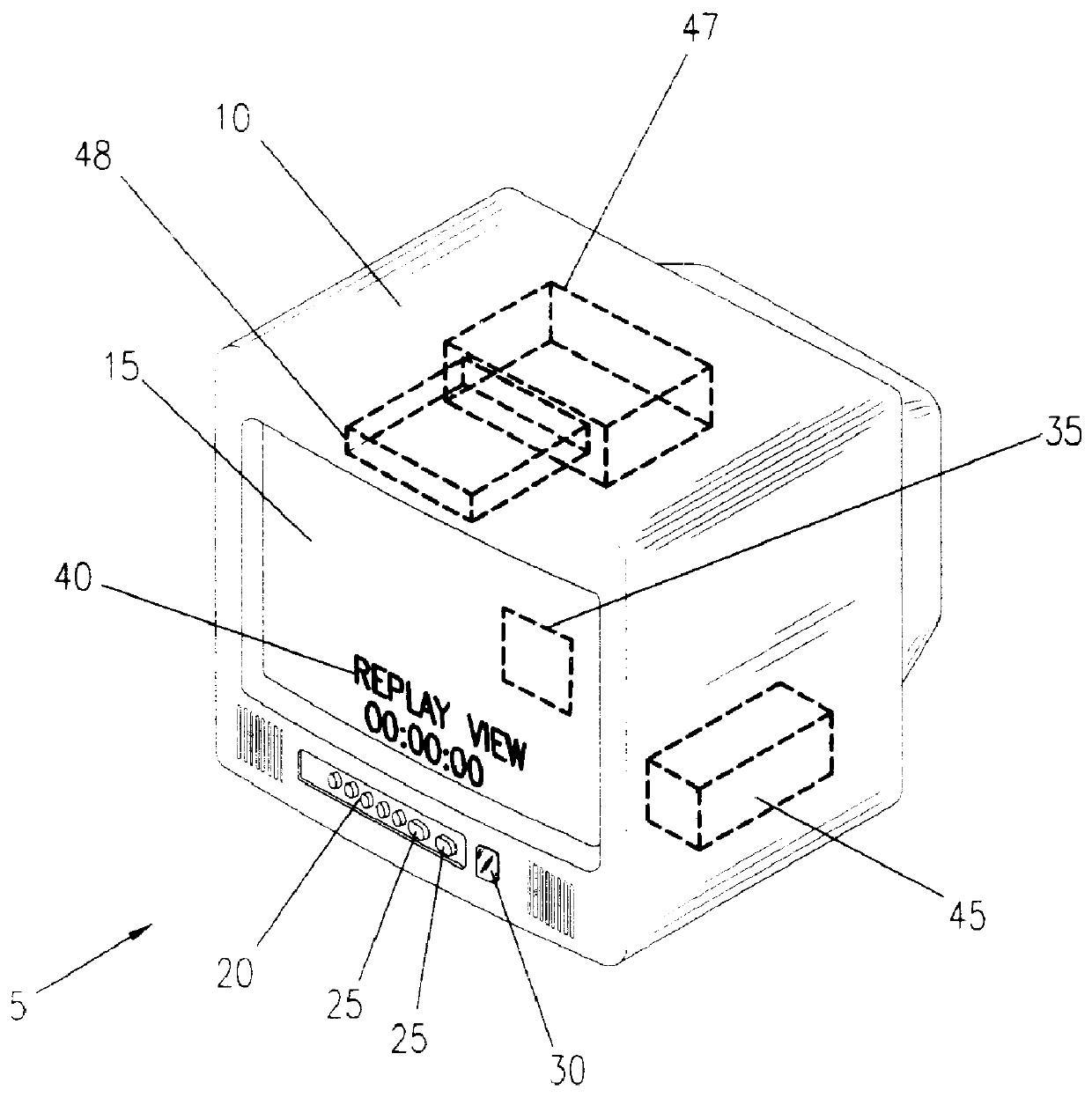
Referring now to FIG. 1, a perspective view of a continuous delay television picture display apparatus 5 is shown in a utilized state according to the preferred embodiment of the present invention. A television receiver 10 of conventional design is depicted with a monitor screen 15 and a control section module 20. The control section module 20 is of a conventional design and contains such elements as a power switch, volume control, channel selections. menu selector, and the like. The control section module 20 possesses similar traits to those units found on conventional current technology television receivers and can take many different final forms. The control section module 20 also contains a review activation switch bank 25 which will activate the review function of the continuous delay television picture display apparatus 5 as will be explained in greater detail hereinbelow. The control section module 20 also contains an infrared interface 30 which interfaces to a ...


PUM


Abstract

An apparatus to aid in the replaying of previously transmitted video signals for the purposed of reviewing missed information on a television receiver is disclosed. Comprising a television tuner whose output signal passes through a video recording system, it utilizes conventional recording technology with the use of a continuous loop tape. The output signal from the tuner is also passed on to a television monitor under normal, standby operation. In the instance where a viewer wishes to review a just viewed signal, such as might occur during a missed word or word sequence such as a telephone number, the viewer is able to switch over to the stored signal on the videotape for a replay of said signal. The replay will continue as many times as desired by the viewer until all necessary information is absorbed. The stored sequence time duration is variable in nature and user selectable. The viewer may view the replayed signal in a picture-in-picture window or may view the replayed signal on the full screen. When completed, the viewer would switch back to real time viewing at which point the video recording process would begin anew. The viewer also has the option of viewing one selected image on a continuous "stop frame" basis and also has the option of producing a hard copy, printed image from an integral printing means.

Description

1. Field of the InventionThe present invention relates generally to television picture displays and more particularly, to an apparatus that allows for the redisplay of any viewed television image within a variable time period of short duration.2. Description of the Related ArtIn the related art, numerous attempts have been made to improve the control features a viewer possesses over a television image. These improvements have ranged from picture-in-picture control schemes to complex digital storage mechanisms using multiple input sources, digital to analog conversion circuits and the like. A search of the prior art did not disclose any patents that read directly on the claims of the instant invention; however, the following references were considered related:The previous art consists of several devices in which the television viewer is able to view images that were previously transmitted. These devices, however, have one or more of the following problems.First, the devices can be co...

Claims


Application Information

Patent Timeline
IPC IPC(8): H04N5/76H04N5/44H04N5/775H04N5/765H04N5/782
CPCH04N5/4448H04N5/76H04N5/775H04N5/765H04N5/782H04N21/414H04N21/42221H04N21/4316H04N21/4325H04N21/4334H04N21/47217
Inventor KRAM, CHRISTINE
Owner KRAM CHRISTINE
Why Eureka
Try Eureka