Antenna arrangement

a technology of antennas and antenna radiation, applied in the field of radio frequency antennas, can solve the problems of reducing the directivity and symmetry of the antenna radiation, affecting the radiation pattern of patch antennas, and affecting the operation of patch antennas, so as to achieve the effect of increasing the bandwidth

Inactive Publication Date: 2000-09-12
APPLE INC
View PDF6 Cites 45 Cited by
  • Summary
  • Abstract
  • Description
  • Claims
  • Application Information

AI Technical Summary

Benefits of technology

Furthermore, the presence of the electrically conductive screen reduces the capacitive interaction between the feeder elements and radiating elements and can thus increase the bandwidth over which the antenna arrangement can be successfully operated.
It is preferred that the spacing between the screen and the feeder elements is at least three, more preferably four, times greater than the spacing between th

Problems solved by technology

When feeding or coupling an electromagnetic signal to the patches the feeder elements will radiate in a non-uniform manner and at different radiation polarisations and so will detrimentally modify the radiation pattern of a patch antenna.
Similarly, incoming radio frequency electromagnetic signals, at different radiation polarisations can cause the feeder lines to resonate and couple spurious electromagnetic signals to the processing circuitry of the antenna.
The electromagnetic interference from the radiating and resonating feeder lines can reduce the directivity and symmetry of the antenna radiation pattern, reduce the front to back sidelobe ratio of the antenna and reduce the polarisation sensitivity of the antenna.
High impedance feeder elements and feeder elements having bends and junctions, such as T-junctions or other splits tend to generate the highest levels of interference.
This makes for a cumbersome and expensive arrangement as it is very cheap and efficient to co-locate the feeder and patch elements in an integrated planer or conformal circuit arrangement, in particular in a microstrip circuit arrangement.
These constraints are generally inco

Method used


Image

  • Antenna arrangement
  • Antenna arrangement
  • Antenna arrangement

Examples


Embodiment Construction

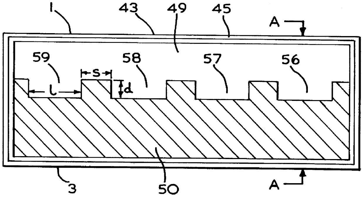
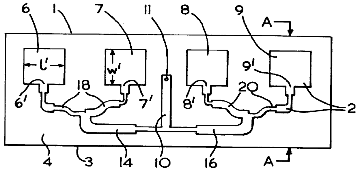
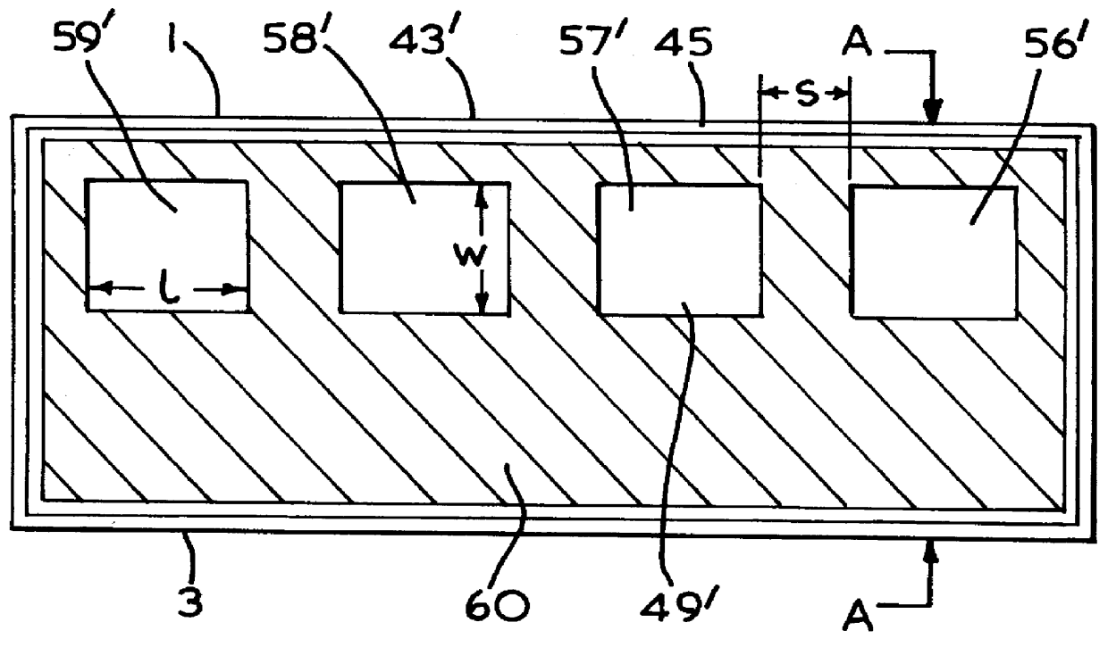
Referring to FIG. 3 which shows an antenna (40) in cross section. The antenna has a two part clamshell housing (42,43) made of, for example, injection moulded plastics material within which is supported a reflecting metal backplate (44). The backplate (44) is formed with four rectangular depressions (46) which correspond to the four microstrip resonant antenna patches (6,7,8,9) shown in FIG. 1. Over the backplate (44) is located a layer of dielectric material (47), such as polystyrene, which has a dielectric constant close to that of air. Alternatively, the layer of dielectric material (47) could comprise an air gap. The polystyrene layer (47) is formed with four rectangular raised portions (48) which fit into the depressions (46) in the reflecting backplate (44). The polystyrene layer (47) insulates the backplate (44) from the printed microstrip antenna and feeder line circuit (2) which is shown in FIG. 1 and which comprises a 37 micron thick copper film (2) printed on a backing sh...


PUM


Abstract

A radio frequency antenna arrangement comprising an array of radiating elements, such as radiating antenna patches, which are co-located in a circuit, such as a microstrip circuit, with feeder elements which couple electromagnetic radiation to the radiating elements. The antenna arrangement has an electrically conductive backplate located behind the circuit, which acts as a groundplane and which is separated from the circuit by a dielectric layer. To reduce electromagnetic interference from the feeder elements which could disrupt the antenna pattern an electrically conductive screen is located directly in front of the feeder elements of the circuit but selectively exposes the array of radiating elements. The screen is spaced from the feeder elements and is not electrically connected to the backplate so that the screen, feeder elements and backplate do not form a triplate structure.

Description

This invention relates to radio frequency antennas having radiating elements which are co-located with feeder lines which couple electromagnetic signals to and from the radiating elements. In particular the present invention relates to radio frequency antennas having radiating patch elements which are formed integrally with feeder lines in a planar or conformal microstrip circuit.A microstip circuit comprises two sheets of electrically conductive material, spaced apart by a dielectric substrate. One of the electrically conductive sheets is etched to provide electrically conducting feed lines and radiating patches, and in cooperation with the other of the electrically conductive sheet, which serves as a ground plane, will support transverse electromagnetic (TEM) waves.Such antennas are commonly used in radio frequency (RF) transceivers of fixed wireless access telecommunications networks.Known fixed wireless access telecommunications networks comprise radio transceivers which are loc...

Claims


Application Information

Patent Timeline
IPC IPC(8): H01Q13/10H01Q13/18H01Q21/00H01Q1/38H01Q21/06
CPCH01Q1/38H01Q13/18H01Q21/0081H01Q21/065
Inventor MCKINNON, JOHN PETER BRUCELLEWELYN, IAN PAULGWYNN, PETER GLANVILLE
Owner APPLE INC
Why Eureka
Try Eureka