Eureka AIR delivers breakthrough ideas for toughest innovation challenges, trusted by R&D personnel around the world.

Synchronous carrier recovery circuit and injection locked oscillator

Inactive Publication Date: 2000-10-17
LUCENT TECH INC +1
View PDF4 Cites 25 Cited by
  • Summary
  • Abstract
  • Description
  • Claims
  • Application Information

AI Technical Summary

Problems solved by technology

However, real world conditions result in variances caused between the actual carrier frequency as ultimately received by the receiver, and the receivers locally generated or recreated carrier frequency.
Thus, as the transmitter or receiver varies in temperature (e.g., as it is taken outside, or as it warms up when it is first turned on), the actual carrier frequency and that generated at the receiver will vary from one another, resulting in a less than accurate demodulation of the modulated signal at the receiver, and thus a less than accurate recovery of the information signal at the receiver.
Unfortunately, the locally generated oscillator must be an extremely stable oscillator, and extremely accurate to the center frequency of the transmitted carrier frequency.
Even so, a locally generated carrier signal is not conventionally capable of sensing drift in the actual received modulated signal.
Unfortunately, locally generated carrier signals suffer from a susceptibility to phase errors which degrade the demodulation performance of the carrier recovery circuit.
For instance, a delay between the sensing of the modulated signal and a recreation of the carrier frequency often causes a phase delay deteriorating frequency synchronization between the carrier frequency and the recreated carrier frequency in the receiver.
While having certain advantages, the inclusion of a PLL in a carrier recovery circuit adds complexity and cost to a receiver.
Moreover, the inclusion of a PLL slows the acquisition time necessary to acquire phase lock with changes in the modulated signal, and thus limits the frequency, modulation, and overall performance of the receiver.

Method used


Image

  • Synchronous carrier recovery circuit and injection locked oscillator
  • Synchronous carrier recovery circuit and injection locked oscillator
  • Synchronous carrier recovery circuit and injection locked oscillator

Examples


Embodiment Construction

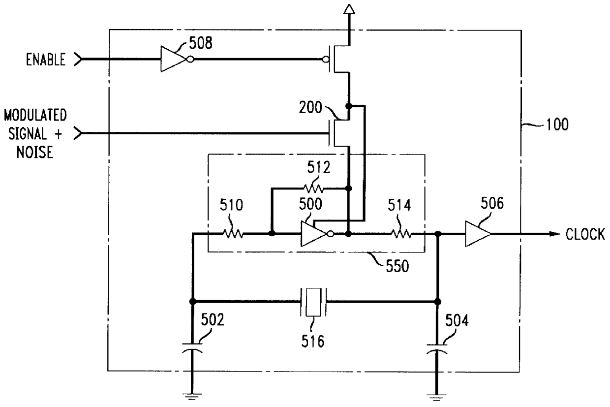
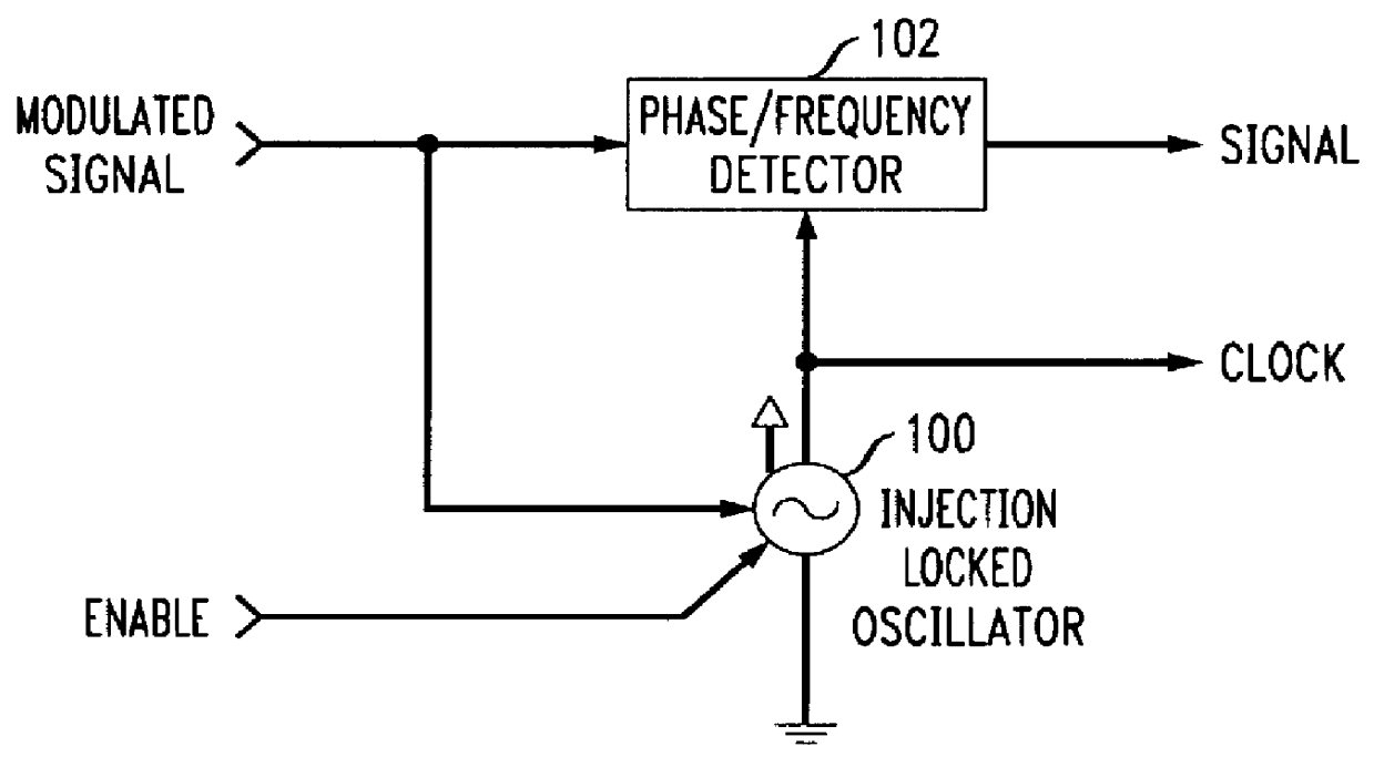
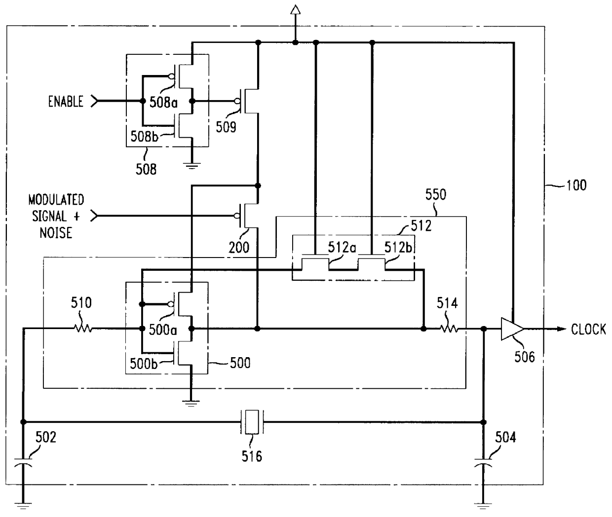
The present invention provides an injection locked oscillator, a specially designed CMOS oscillator that can be used for carrier recovery. The use of the injection locked oscillator eliminates the need for a PLL in a carrier recovery circuit which synchronizes with an incoming carrier signal. The injection locked oscillator functions as an adaptive high Q band-pass filter which is capable of following drift in the incoming carrier signal so that synchronization can be achieved.

The disclosed embodiment of an injection locked oscillator forms a crystal oscillator tuned to the expected center frequency of the carrier signal. Importantly, the injection locked oscillator includes a synchronizing input corresponding to the received signal. The present invention, while in no way limited to any particular carrier signal, is especially suitable for use with low end cordless telephones and other 10 to 100 or 200 MHz low power, wireless applications.

FIG. 1 shows a synchronized carrier frequenc...


PUM


Abstract

A simple carrier recovery circuit capable of accurately detecting and synchronizing an incoming carrier frequency without the use of a phase locked loop (PLL) is provided. Instead of a PLL, the carrier recovery circuit includes an injection locked oscillator. The injection locked oscillator includes an input for connection to the received modulated signal. The gain of an inverter stage of a amplifier in the injection locked oscillator is modulated by the received modulated signal using an injection transistor connected between the power source and the output of the inverter stage. The gate of the injection transistor receives a signal corresponding to the received modulated signal.

Description

1. Field of the InventionThis invention relates to carrier signal recovery, and more particularly to an injection locked oscillator for use with a carrier recovery circuit.2. Background of Related ArtRadio signals are utilized in many wireless applications for carrying an information signal from a transmitter to a receiver. Often the underlying information signal being transmitted is modulated for transmission at radio frequencies. Many modulation techniques exist for radio frequency (RF) communications, e.g., amplitude modulation (AM), frequency modulation (FM), and quadrature amplitude modulation (QAM). In most modulation techniques, a carrier signal is required to carry the information signal, whether it be modulated in amplitude, frequency, and / or phase.For instance, in FM, the information signal is added to or frequency modulated (FM) with the carrier signal, and amplified for transmission to the receiver. The transmitted signal thus comprises the original information signal im...

Claims


Application Information

Patent Timeline
IPC IPC(8): H03K3/354H03K3/00H03D3/24H03L7/06H03D3/00H04L7/027H03L7/24H03B5/12H03B5/08H04L7/033
CPCH03B5/364H03B5/366H03D3/24H03K3/354H03L7/0805H03L7/24H04L7/027H03L7/06H04L7/033
Inventor MA, ZHIGANG
Owner LUCENT TECH INC
Why Eureka
Eureka Blog
Learn More