Manufacturing method of ink jet head

a manufacturing method and ink jet technology, applied in the field of ink jet head manufacturing, can solve the problems of deteriorating image quality, reducing the thickness of the ink supply member, and unable to reduce the distance between the recording material and the ink ejection outl

Inactive Publication Date: 2000-10-31
CANON KK
View PDF13 Cites 172 Cited by
  • Summary
  • Abstract
  • Description
  • Claims
  • Application Information

AI Technical Summary

Problems solved by technology

This arrangement is used because if the ink supply is effected from the ink ejection pressure generation element formation side (ink ejection outlet formation surface), an ink supply member has to be located between the ink ejection outlet and the recording material such as paper or textile, and in such a case, the distance between the recording material and the ink ejection outlet cannot be reduced, because it is difficult to reduce the thickness of the ink supply member, with the result that the image quality is deteriorated because of the deterioration of the positional accuracy of the ink droplets that are shot.
This is because if a method is used in which a resin material layer for the ink flow passage wall dissolved in a solvent is applied (solvent coating such as spin coating, roller coating), the resin material flows into the through-opening, the result being that the film formation is not uniform.
However, the use of the dry film involves the drawbacks, as follows.
For example, the film formation accuracy is poorer than in the film formation technique of spin coating or the like.
The above-described photo-polymerization dry film has poor coating property, so that formation of thin film more than 15 .mu.m thick is difficult.
Generally, high resolution and high aspect ratios are difficult to provide.
Stability against time elapse is poor (property of transfer to the substrate or the patterning property).
With the method, the positional accuracy between the ink ejection pressure generation element and ink ejection outlet is very high, but for the formation of the soluble resin material layer, the dry film has to be used, and therefore, the above-described drawbacks of the dry film still apply.

Method used


Image

  • Manufacturing method of ink jet head
  • Manufacturing method of ink jet head
  • Manufacturing method of ink jet head

Examples


embodiment 1

(Embodiment 1)

In this embodiment, the ink jet head was manufactured through the processes showed in FIG. 1-FIG. 10. Silicon oxide films are formed on both surfaces of the silicon wafer having a crystal face direction and having a thickness of 500 .mu.m through heat oxidation (thickness is 2.75 microns). Then, electrothermal transducer elements serving as the ejection energy generating elements and electrodes for control signal input for operating the elements, are formed on the silicon oxide film (the surface having the electrothermal transducer element is called the front surface or surface, hereinafter).

Here, the back side of the silicon wafer is provided with a silicon oxide film formed through the heat oxidation, and therefore, there is no need of additional mask member for the anisotropic etching of the silicon. The silicon oxide film on the back side is removed through plasma etching by the CF.sub.4 gas only at the portion corresponding to the ink supply port (FIG. 3).

Subsequ...

embodiment 2

(Embodiment 2)

In this embodiment, the ink jet head was prepared through nozzle process, anisotropic etching, and anisotropic etching stop layer removal process, in the order named.

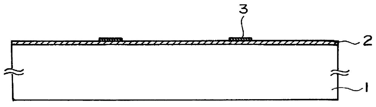
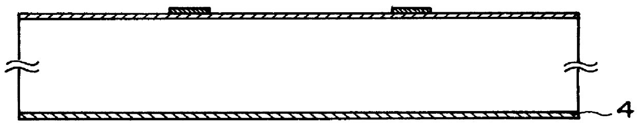
On the surface of the silicon wafer 1 having a thickness of 500 .mu.m and having crystal face direction , electrothermal transducer elements 3 as the ejection energy generating elements and a driving circuit for operating the elements, were formed. Then, a silicon nitride film 2 was formed on the surface of the silicon wafer as a stop layer against the anisotropic etching. The silicon nitride film 2 functions also as a protecting film for the electrothermal transducer elements. Then, a silicon nitride film was formed on the back side of the wafer as a mask member 4 against the anisotropic etching (FIG. 2).

Subsequently, in this embodiment, nozzle portions are formed. Similarly to Embodiment 1, the ink flow path molds were formed using PMER as the soluble resin material layer, and the coating resin material ...

embodiment 3

(Embodiment 3)

In this embodiment, the use was made with the method disclosed in Japanese Laid Open Patent Application No. SHO-62-264957 Specification, for this invention.

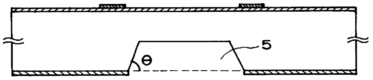
Up to the stage of formation of the ink supply port by anisotropic etching of silicon, the steps are substantially the same as in Embodiment 1 (FIG. 5).

Then, the resin material layer 10 for constituting the nozzle, was formed by spin coating, and the patterning using light projection, and development were carried out (FIG. 13).

Here, since the surface of the silicon wafer is flat, the spin coating is usable for the film formation. This is advantageous as follows.

The film formation is possible with high accuracy with any given film thickness even to such an extent of not more than 15 .mu.m which is difficult with the use of dry film, so that the design latitude was increased.

Since the ink does not fall into the ink supply port as contrasted to the case of use of the dry film, ink supply port may be disposed closer to ...


PUM


Abstract

A manufacturing method for an ink jet head having an ink ejection pressure generation element for generating energy for ejecting ink, and an ink supply port for supplying the ink to an ink jet head, including the steps of preparing a silicon substrate; forming, on a surface of the silicon substrate, the ink ejection pressure generation element and silicon oxide film or silicon nitride film; forming anti-etching mask for forming an ink supply port on a back side of the silicon substrate; removing silicon on the back side of the silicon substrate at a position corresponding to the ink supply port portion through anisotropic etching; forming an ink ejection portion on a surface of the silicon substrate; and removing the silicon oxide film or silicon nitride film from the surface of the silicon substrate of the ink supply port portion.

Description

FIELD OF THE INVENTION AND RELATED ARTThe present invention relates to a manufacturing method for ink jet heads for generating a recording liquid droplet usable with an ink jet type apparatus. More particularly, the present invention relates to a manufacturing method for an ink jet head of the so-called side shooter type which ejects the recording liquid droplet in a direction substantially perpendicular to the surface having an ink ejection pressure generation element.In the so-called side shooter type ink jet head, wherein the ink is ejected upwardly from the ink ejection pressure generation element, a substrate having an ink ejection pressure generation element (ejection energy generating element) is provided with a through-opening (ink supply port) to supply the ink from the back side (not having the ink ejection pressure generation element) of the substrate, as disclosed in Japanese Laid Open Patent Application No. SHO-62-264957 or U.S. Pat. No. 4,789,425. This arrangement is u...

Claims


Application Information

Patent Timeline
Patent Type & Authority Patents(United States)
IPC IPC(8): B41J2/16
CPCB41J2/1603B41J2/1628B41J2/1645B41J2/1631B41J2/1639B41J2/1629B41J2/01
Inventor OHKUMA, NORIO
Owner CANON KK
Why Eureka
Try Eureka