Material delivery system

a technology of material delivery and delivery system, which is applied in the direction of transportation items, loading/unloading vehicle arrangment, mechanical machines/dredgers, etc., can solve the problems of non-direct attachment of reagent storage containers in the prior art system, general inability to properly supply and control reagent delivery, and non-uniform hardness and consistency in the treated area

Inactive Publication Date: 2000-11-28
J A JONES ENVIRONMENTAL SERVICES
View PDF20 Cites 47 Cited by
  • Summary
  • Abstract
  • Description
  • Claims
  • Application Information

AI Technical Summary

Benefits of technology

According to yet another preferred embodiment of the invention, a hopper valve is located at the outlet of the supply hopper for effecting controlled release of material from the supply hopper to the supply line.

Problems solved by technology

Moreover, the prior art system does not include a reagent storage container attached directly to the stick of the excavator and adapted for being carried downwardly into the lagoon to treat the lagoon from the bottom up.
These system are generally incapable of properly supplying and controlling reagent delivery to the specific area being treated.
Such problems typical result in treated areas having non-uniform hardness and consistency.

Method used


Image

  • Material delivery system
  • Material delivery system
  • Material delivery system

Examples


Embodiment Construction

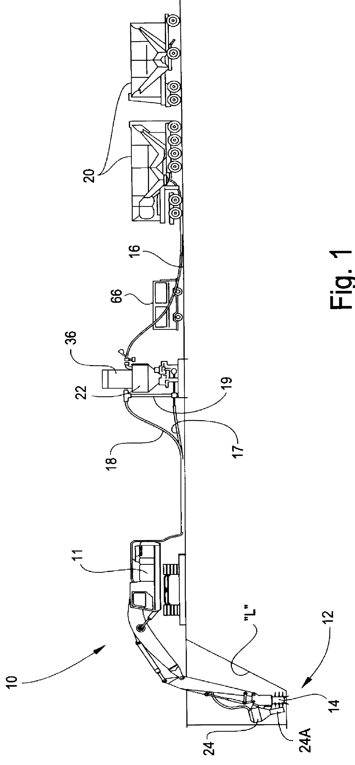
Referring now specifically to the drawings, a reagent delivery system according to the present invention is illustrated in FIG. 1 and shown generally at reference numeral 10. The delivery system 10 employs a standard industrial excavator 11, such as the CAT 375L manufactured by Caterpillar, Inc. of Aurora, Ill., for delivering dry reagent below the surface of a sludge lagoon "L". The dry reagent is a mixture of fly ash and cement which reacts with the sludge waste to solidify the lagoon "L". The ratio of fly ash to cement is about 1:1 or 1:2 depending on the moisture content of the area to be treated. The excavator 11 includes direct reading pressure and flow gauges, a computerized depth / grade and slope recorder and indicator system, and has laser target and laser survey capabilities. The total length of the boom and stick of the excavator 11 is between 30-40 feet.

A mixer assembly 12 is pivotably mounted on the stick of the excavator 11 and includes a pair of spaced, axial, counter-...


PUM


Abstract

A material delivery system conveys material from a supply location at or above an area surface to a working location below the area surface. The delivery system includes a supply hopper located at the supply location and having an inlet for receiving material to be conveyed and an outlet for discharging material. An injection hopper is adapted for mounting on a movable working arm of a self-propelled vehicle, and has an inlet for receiving material and an outlet for discharging material. The arm of the vehicle carries the injection hopper below the area surface to the working location. A supply line is connected to the outlet of the supply hopper and to the inlet of the injection hopper for conveying material from the supply location to the working location.

Description

TECHNICAL FIELD AND BACKGROUND OF THE INVENTIONThis invention relates to a material delivery system applicable in the environmental treatment of solid, semisolid, and liquid waste. Such waste is commonly generated as a by-product of industrial plants, and then stored in man-made sludge lagoons for later processing. The invention conveys sludge-hardening reagent from a supply location at or above the sludge surface to a working location below the surface in the lagoon. A rotating mixer assembly blends the reagent and sludge together. The resulting mixture reacts causing the lagoon to harden sufficient for supporting trucks and other vehicles. After treatment, the solidified lagoon can be capped with a protective layer and used as a parking lot, equipment storage area, or the like.According to one prior art waste treatment system, an industrial excavator including rotating tines 5-15 feet long is used for injecting and blending a reagent slurry below the surface into a waste lagoon. U...

Claims


Application Information

Patent Timeline
Patent Type & Authority Patents(United States)
IPC IPC(8): B09B1/00
CPCB09B1/00
Inventor CURTIS, DON V.ROLLINS, WILLIAM V.LABUS, EDWARD J.
Owner J A JONES ENVIRONMENTAL SERVICES
Why Eureka
Try Eureka