Method for laser twist welding of compressor blisk airfoils

a technology of laser twist welding and compressor blisk, which is applied in the direction of machines/engines, mechanical equipment, manufacturing tools, etc., can solve the problems of not being able to repair large-scale areas, not being able to accept more significant damage, and not being able to manufacture blisk components by all known methods of manufacture (milling, electrochemical machining)

Inactive Publication Date: 2001-01-09
GENERAL ELECTRIC CO
View PDF11 Cites 111 Cited by
  • Summary
  • Abstract
  • Description
  • Claims
  • Application Information

AI Technical Summary

Benefits of technology

A fixture, a local dry box, provides a convenient means for enclosing a portion of the substrate being welded, usually several airfoils at a time, to allow a clean dry argon atmosphere to be maintained over the weld pool and in the to region adjacent to the welding. The fixture also encloses at least a tip of the weld nozzle. This results in deposits having minimal contamination, which is essential when welding titanium materials. The need for gas shielding in the vicinity of the weld does not limit the process to the use of compact dry box; a larger argon filled enclosure that covers the entire part could be used and may reduce weld repair cycle time.
The apparatus and process of the present invention also permit repair on substrate materials having a thickness of 0.125 inches and less, without burn-through and without adversely affecting the thin portion of the substrate opposite the weld repair.

Problems solved by technology

Blisk components manufactured by all known methods of manufacture (milling, electrochemical machining) are subject to foreign object damage (F.O.D.) of the airfoils.
In either case, repair of the damaged region is often desirable due to the high replacement cost of the components.
While this repair method is suitable for minor airfoil edge damage, it is not acceptable for more significantly damaged areas due to imbalance problems and potential mechanical property degradation.
While the technology described in these patents has been used to successfully repair minor damage to titanium (Ti 6-4) materials by applying the same feed or replacement material as the damaged base materials, no large scale repairs have been accomplished, and no repairs have been performed by depositing a feed or replacement material that is different than the substrate base material.
One of the problems experienced in attempts to manufacture and repair items using laser welding techniques such as described above include low integrity welds.
Contamination due to oxygen and nitrogen causes a brittle weld repair, which is an unacceptable result for an airfoil repair.
Impact due to foreign object ingestion by a gas turbine engine could result in a failure of the repaired area, that could lead to separation of the portion of the blade above the repaired area.
Drawbacks with the system set forth in these patents include operator fatigue.
Furthermore, as noted in the prior art patents, the systems are sensitive and failure to override in a timely fashion can lead to an unacceptable region of repair.
However, problems with this technique are frequent loss of the protective argon gas over the molten metal, as set forth above.
Spattering of molten metal onto adjacent blades and the undesirable heating of adjacent blades from laser energy reflections from the weld pool due to the close arrangement of blades around the blisk pose additional problems.
Without the shields, such reflections cause overheating of adjacent blades.

Method used


Image

  • Method for laser twist welding of compressor blisk airfoils
  • Method for laser twist welding of compressor blisk airfoils
  • Method for laser twist welding of compressor blisk airfoils

Examples


Embodiment Construction

The present invention is directed to an improved method for performing LTW repairs. Because the disks and blades of compressors are being manufactured as integral structures, an improved method of repairing blisks either prior to being placed into service because of manufacturing operations resulting in components not in conformance to drawing requirements or after removal from service due to service-induced damage is required.

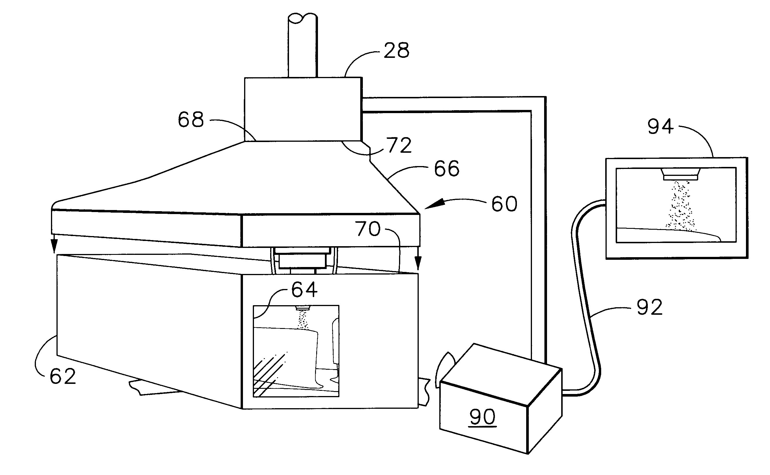
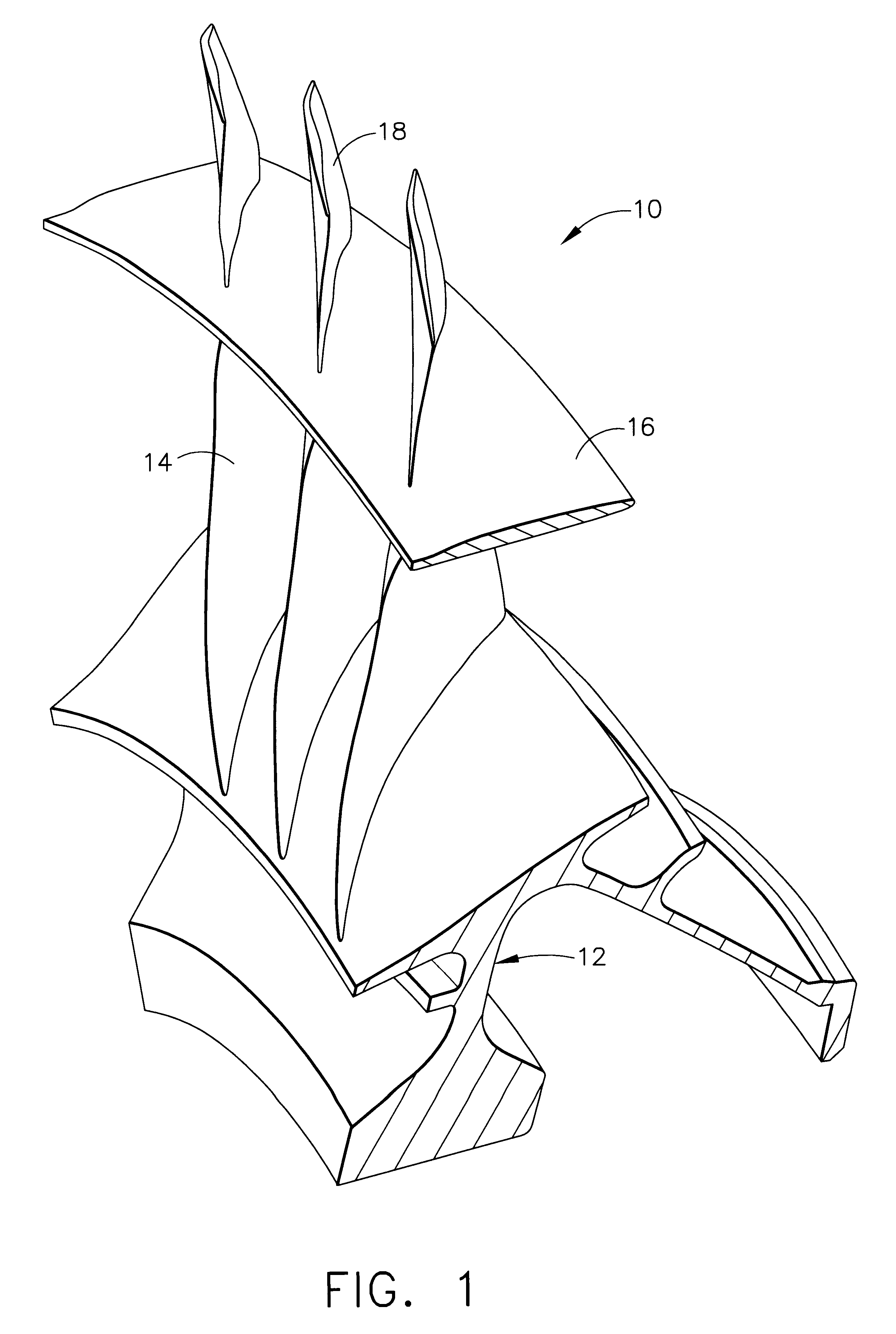
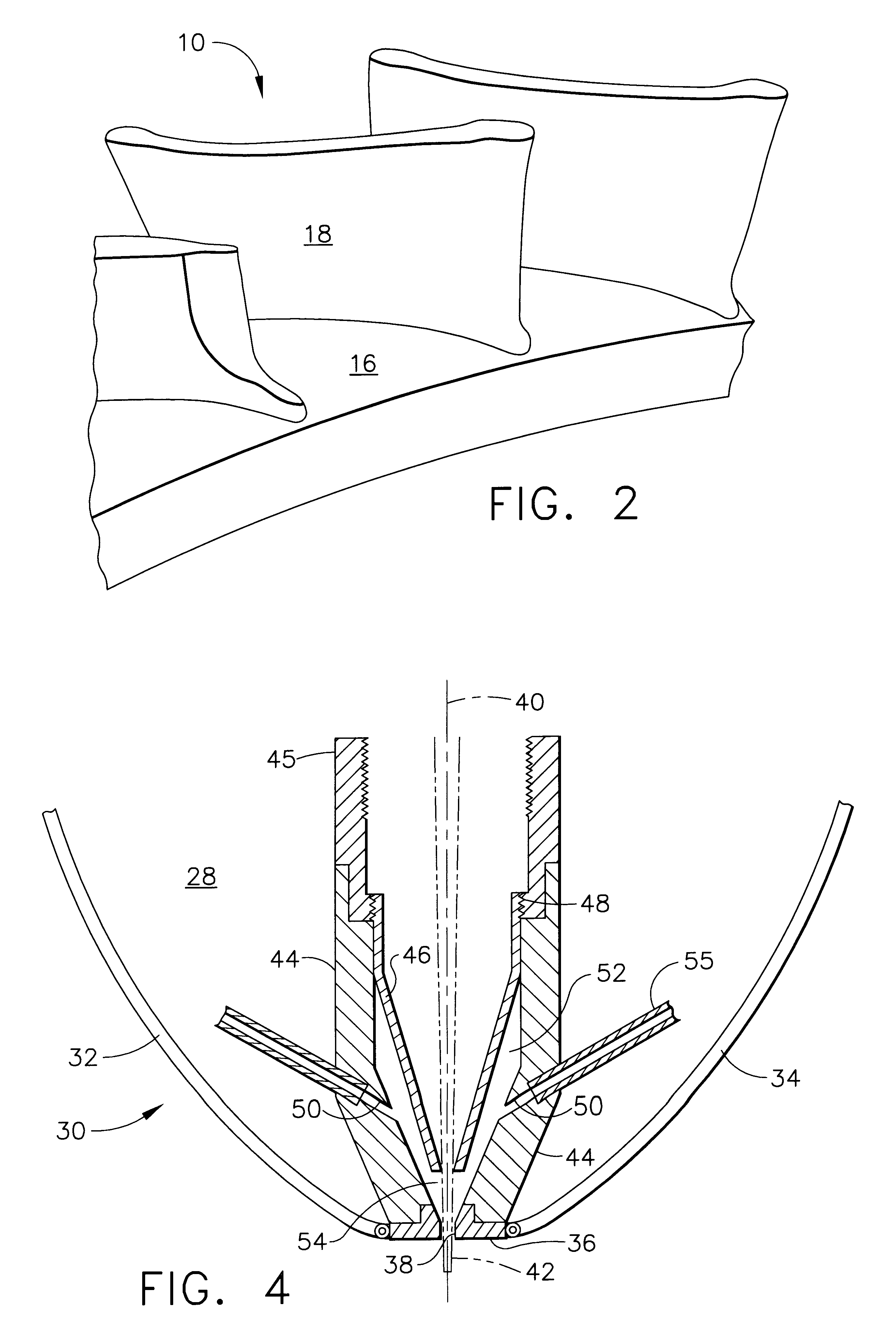
A typical blisk assembly is shown in FIG. 1. This blisk assembly is similar to the blisk for a XCT46 stage 1. This blisk assembly 10 includes a central disk 12, with compressor blades 14 extending outward from the central disk, as is typical with all blisk and disk / blade assemblies. However, this blisk also incorporates an integral 360.degree. midspan shroud 16 outward from the central disk as is sometimes found in compressors, with outer blade portions 18 extending outwardly from the midspan shroud 16. This is shown in an exploded view in FIG. 2. The apparatu...


PUM

PropertyMeasurementUnit
widthaaaaaaaaaa
thicknessaaaaaaaaaa
thicknessaaaaaaaaaa

Abstract

A method for repair welding a titanium compressor blisk using laser twist welding. A blisk assembly has damaged portions removed. The surface to be repaired is provided with a predetermined geometry. The portions to be repaired are surrounded by a fixture which contains a laser nozzle. The fixture can provide a protective atmosphere to the area under repair while also shielding adjacent areas from damage resulting form welding. The welding is accomplished using preprogrammed patterns. The welding within the fixture is monitored remotely and is adjusted when stand-off between the weld nozzle and the molten metal are not within a predetermined range.

Description

1. Field of the InventionThe invention relates to improved apparatus and method for repairing a metallic portion of an article using a metal powder and a laser beam, and specifically to repairing a blisk assembly such as are found in gas turbine engines.2. Description of the Prior ArtAn aircraft gas turbine engine or jet engine draws in and compresses air with an axial flow compressor, mixes the compressed air with fuel, burns the mixture and expels the combustion product through an axial flow turbine that powers the compressor. The compressor includes a disk with blades projecting from its periphery. The disk turns rapidly on a shaft, and the curved blades draw in and compress air. In the past, the blades and the disk were structures that were manufactured separately and assembled together. More recently, the blades have been manufactured integral with the disk forming a single integral structure known as a blisk.Blisk components manufactured by all known methods of manufacture (mi...

Claims


Application Information

Patent Timeline
Patent Type & Authority Patents(United States)
IPC IPC(8): B23K26/00B23K26/12B23K26/34B23P6/00F01D5/00
CPCB23K26/032B23K26/12B23K26/123B23K26/125F01D5/005B23K26/322B23K26/345B23K26/127B23P6/007Y10T29/49318B23K26/32B23K26/342B23K2103/14B23K2103/18
Inventor ALESHIN, STEPHENBRUNCK, MICHAEL J.ENGLISH, CHRISTOPHER L.
Owner GENERAL ELECTRIC CO
Why Eureka
Try Eureka