Magnetic tumble stirring method, devices and machines for mixing in vessels

a technology of magnetic tumble and stirring device, which is applied in the direction of biomass after-treatment, transportation and packaging, laboratory glassware, etc., can solve the problems of not being widely used, not being able to adequately resuspend particulates, and costing .about.$30,000, so as to enhance the strength of attraction and the effect of great magnetic coupling

Inactive Publication Date: 2001-01-23
V & P SCI
View PDF11 Cites 143 Cited by
  • Summary
  • Abstract
  • Description
  • Claims
  • Application Information

AI Technical Summary

Benefits of technology

The present invention provides a method of mixing the contents of each of a two-dimensional array of vessels, each vessel having a vertical axis as defined when the vessel is disposed for the mixing of said contents, the method comprising the steps of:
(a) placing magnetic stirrers within said vessels; and
(b) when the vessels are disposed for the mixing of said contents, rotating a permanent magnet about a non-vertical axis of rotation that is so disposed adjacent the array that said rotation of the magnet provides magnetic flux lines that rotate through 360 degrees within a non-horizontal plane within each of the vessels to thereby cause the magnetic stirrers therein to tumble in at least one direction that is other than about the vertical axis of each vessel;
whereby the contents of each vessel containing a said magnetic stirrer are mixed by the tumbling of said magnetic stirrer.
Thus it is the object of the method, devices and machines to provide a very simple process of uniformly mixing the contents of thousands of vessels and microplate wells (6 well, 12 well, 24 well, 48 well, 48 deep well, 96 well, 384 well, 864 well, 1536 well, 10,000 well and the deep well, "U" bottom, "V" bottom, PCR and other versions of those microplates) at the same time. We have made stainless steel magnetic stir discs, bars and dowels of different dimensions, shapes an

Problems solved by technology

However because of the combination of the small well diameter, the tall height of the column of liquid and the significant attraction of liquid surface tension forces to the walls of small diameter wells (especially in the 48, 96, 384, 864, 1536 and 10,000 well microplates) it is not possible to adequately resuspend particulates, stimulate the growth of microorganisms, break up aggregates, break open cells, aerate gases in to liquids, emulsify two liquids, mix two liquid reagents, or to dissolve a solid in a liquid by simple agitation on an orbital shaker, vortexer, rocker platform, bubbler or by vibration without generating a force so violent that it would throw the liquids out of the miniature vessels.
Because of these technical and cost considerations this system has not been widely used.
Recently Robbins Scientific introduced the "Hydra" work station which will pipet and mix 96 wells at a time but it costs .about.$30,000 and is still laborious as the pipets must be washed between wells.
Furthermore it would be economically impossible to do continuous mixing of multiple microplates simultaneously by pipetting.
In addition it would be difficult to place a large robotic workstation in an incubator if microorganisms we

Method used


Image

  • Magnetic tumble stirring method, devices and machines for mixing in vessels
  • Magnetic tumble stirring method, devices and machines for mixing in vessels
  • Magnetic tumble stirring method, devices and machines for mixing in vessels

Examples


Embodiment Construction

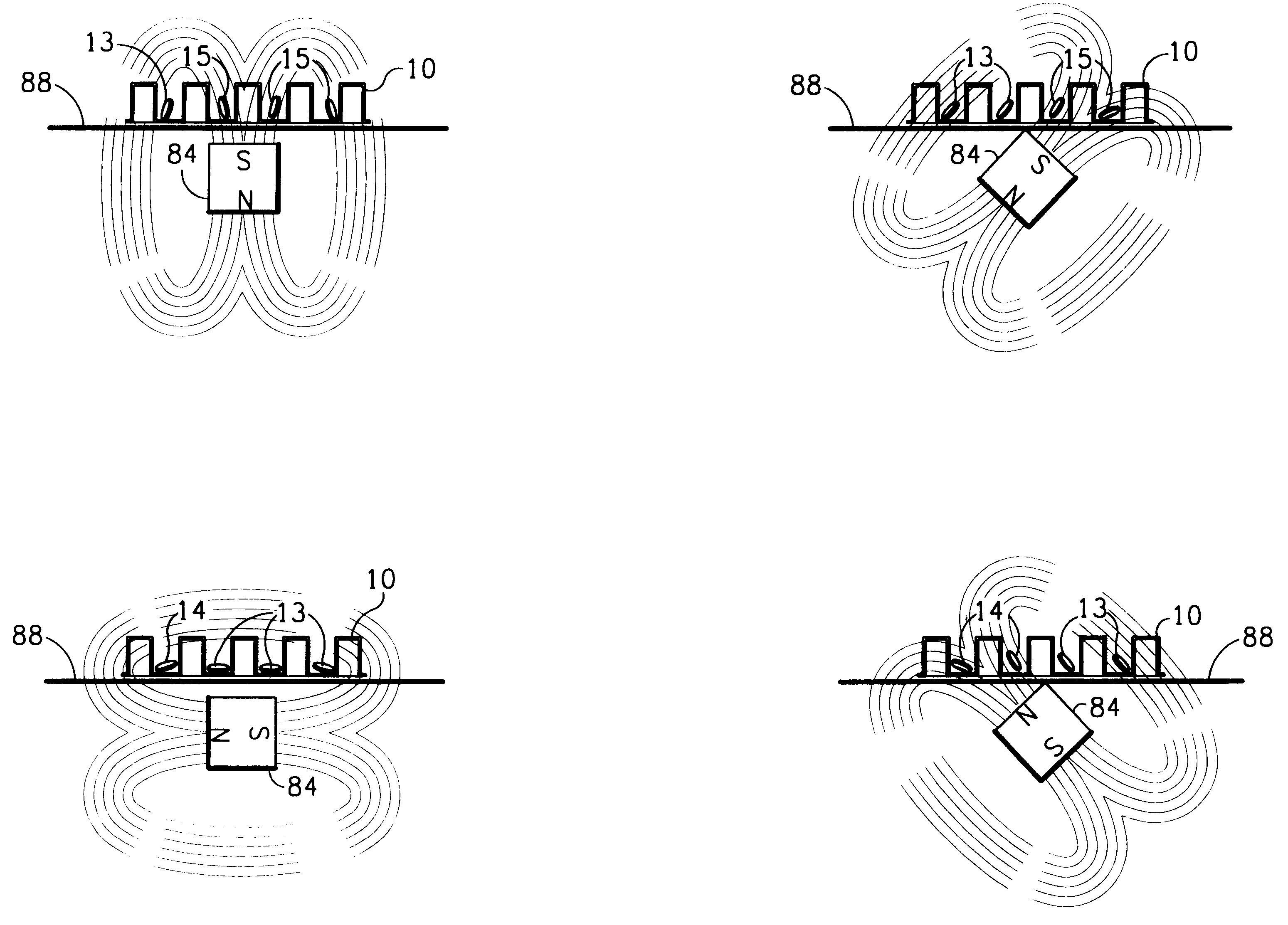
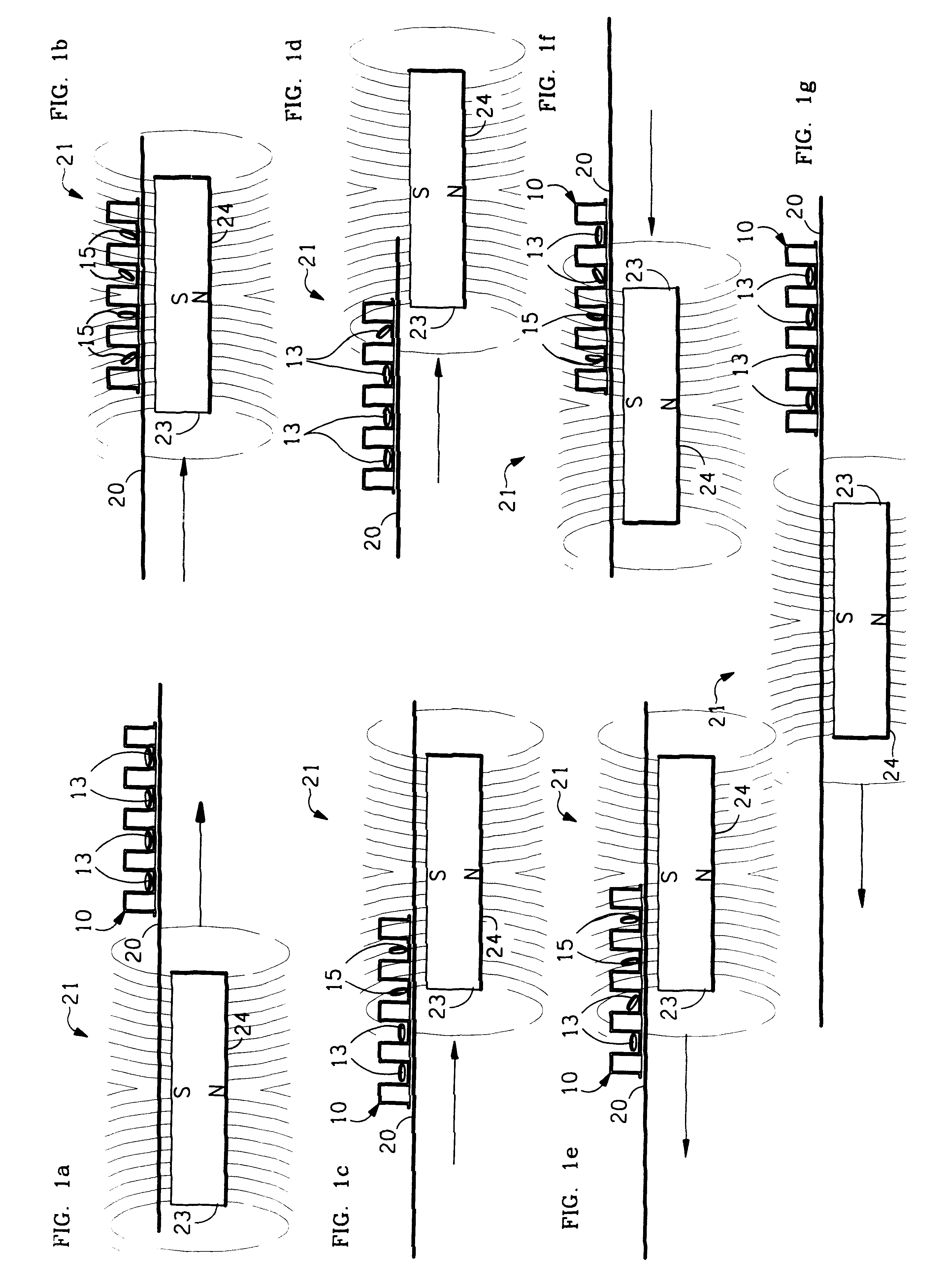
FIGS. 1a, b, c and d, illustrate how tumble stir discs (13) are moved and tumbled in the presence of the vertically aligned magnetic field (21) of a reversing moving drive magnet with the south pole up (23). As the drive magnet (23) moves, the discs (15) tumble as their magnetic north pole magnetically couples to the magnetic field (21) of the drive magnet's south pole (23). The whole tumbling process is reversed when the direction of the drive magnet (23) is reversed in FIG. 1e, f and g.

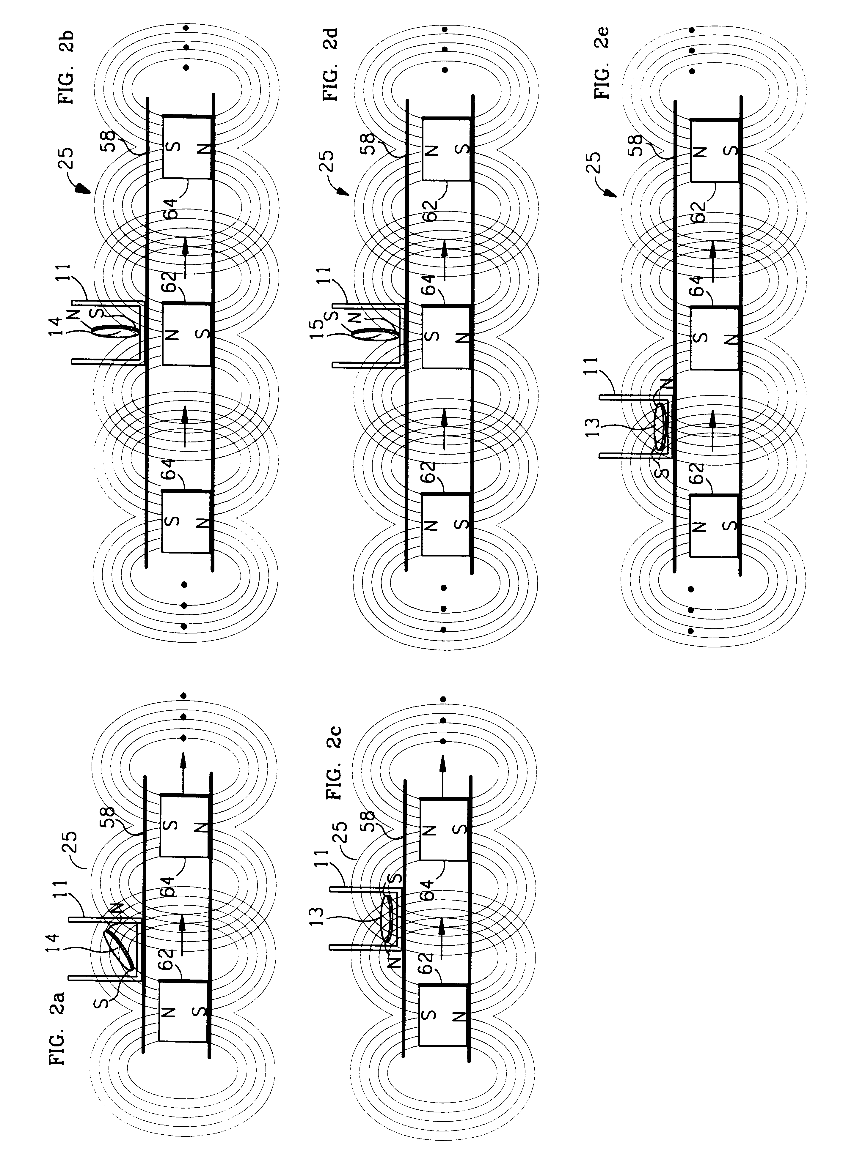
FIGS. 2a, b, c, d, and e illustrate how tumble stir discs (13) are moved and tumbled continuously in the same direction in the presence of vertically aligned alternating north south drive magnetic field. As the drive magnetic array (62 and 64) moves, the discs (14) tumble as their magnetic south pole magnetically couples to the magnetic circuit (25) between drive magnet 62 and drive magnet 64 producing a continuous tumbling action in the same direction as the magnetic circuit moves laterally to the ...


PUM


Abstract

The invention provides a simple method, device and several machines for simultaneously stirring thousands of vessels or wells of microplates in a robust manner and with economy. This method uses the simple principle of magnetic stirrers aligning themselves to a vertical driving magnetic field placed beneath them and moving laterally or by moving the vessels over a stationary magnetic field or by spinning the drive magnets, or by using a modulating/reversing electromagnetic field to produce the moving effect. Each vessel contains a magnetic disc, bar, dowel or other shape (stirrers) which in it's magnetic attraction to the vertical driving magnetic field will cause it to move and align it's magnetic field as the opposite poles of the drive magnet and the stirrer attract each other. The attraction of the stirrers to the vertical driving magnetic field causes the stirrers to stand on end and tumble as the stir devices try to align to the opposite moving magnetic pole. The stirrers tumble because the walls of the vessels or friction with the vessel bottom prevents their lateral movement.

Description

1. Field of InventionThis invention provides a method, devices and machines to uniformly and simultaneously mix in vessels. The purpose is to provide a robust method, economical devices and very simple machines to uniformly stir the contents of one vessel or thousands of vessels or microplate wells (6 well, 12 well, 24 well, 48 well, 96 well, 384 well, 864 well, 1536 well, 10,000 well and the deep well, "U" bottom, "V" bottom, PCR and other versions of those microplates) at the same time.2. Description of Prior ArtSuspending particulates in liquids, breaking up aggregates, aeration of gases in liquids, dissolving solids in liquids, emulsifying two liquids or mixing liquids together has usually been accomplished in large vessels, bottles, flasks and test tubes by magnetic horizontal spin stirring, orbital shakers, vortexing, rocking platforms, bubblers or vibrators. In an effort to miniaturize many of the operations that were done in bottles, flasks and test tubes, scientists have sh...

Claims


Application Information

Patent Timeline
IPC IPC(8): B01F13/08B01F13/00
CPCB01F13/0818B01F33/452
Inventor CLEVELAND, PATRICK H.MARKLE, JOHN R.
Owner V & P SCI
Why Eureka
Try Eureka