Eureka AIR delivers breakthrough ideas for toughest innovation challenges, trusted by R&D personnel around the world.

Method and apparatus for producing rotationally symmetrical valve seat faces of high surface quality in valves

Inactive Publication Date: 2001-01-30
ROBERT BOSCH GMBH
View PDF6 Cites 7 Cited by
  • Summary
  • Abstract
  • Description
  • Claims
  • Application Information

AI Technical Summary

Benefits of technology

The method of the invention and the apparatus of the invention have the advantage over the prior art that in a simple way, an improvement in the surface quality of rotationally symmetrical valve seat faces is created, so that the tightness of the valve in cooperation with sealing faces on the movable valve part is substantially improved without requiring metal-cutting machining. The elastic deformation between the valve seat face and the tool body resulting from Hertzian stress produces a relatively broad, smoothed trace on the valve seat face, in which the surface roughness is reduced, without significantly indenting the valve seat face of the valve seat body. During the assembly of the valve with the valve seat body treated according to the invention, in contrast to a valve seat body treated by the known method, no predetermined pairing with a movable valve part has to be maintained.By the provisions recited herein advantageous further features of and improvements to the method and the apparatus for performing the method are possible.It is especially advantageous for a tool body axis of rotation, about which the tool body is rotated, to be inclined relative to a valve seat body axis extending longitudinally of the valve seat body, as a result of which a lubricant introduced into a region of the area of contact between the valve seat body and the tool body is repeatedly reintroduced to the area of contact and a layer of lubricant builds up at the area of contact, which prevents "seizing" between the valve seat body and the tool body. It is also advantageous to embody the valve seat body chucking unit of the apparatus from a receiving body and a holding-down body, which makes easy insertion, fixation and removal of the valve seat body possible.An exemplary embodiment of the invention is shown in simplified form in the drawing and described in further detail in the ensuing description.FIG. 1 shows an apparatus for producing rotationally symmetrical valve seat faces in valves, andFIG. 2 shows a detail of the apparatus of FIG. 1 on a larger scale.

Problems solved by technology

Although this produces surfaces with a very high surface quality that assures good tightness of the valve, nevertheless it is disadvantageous for the assembly of the valve that the individual pairings of the movable valve part and valve seat body that have been treated by the known method must be retained, which is a problem in terms of the sequence of assembly.

Method used


Image

  • Method and apparatus for producing rotationally symmetrical valve seat faces of high surface quality in valves
  • Method and apparatus for producing rotationally symmetrical valve seat faces of high surface quality in valves
  • Method and apparatus for producing rotationally symmetrical valve seat faces of high surface quality in valves

Examples


Embodiment Construction

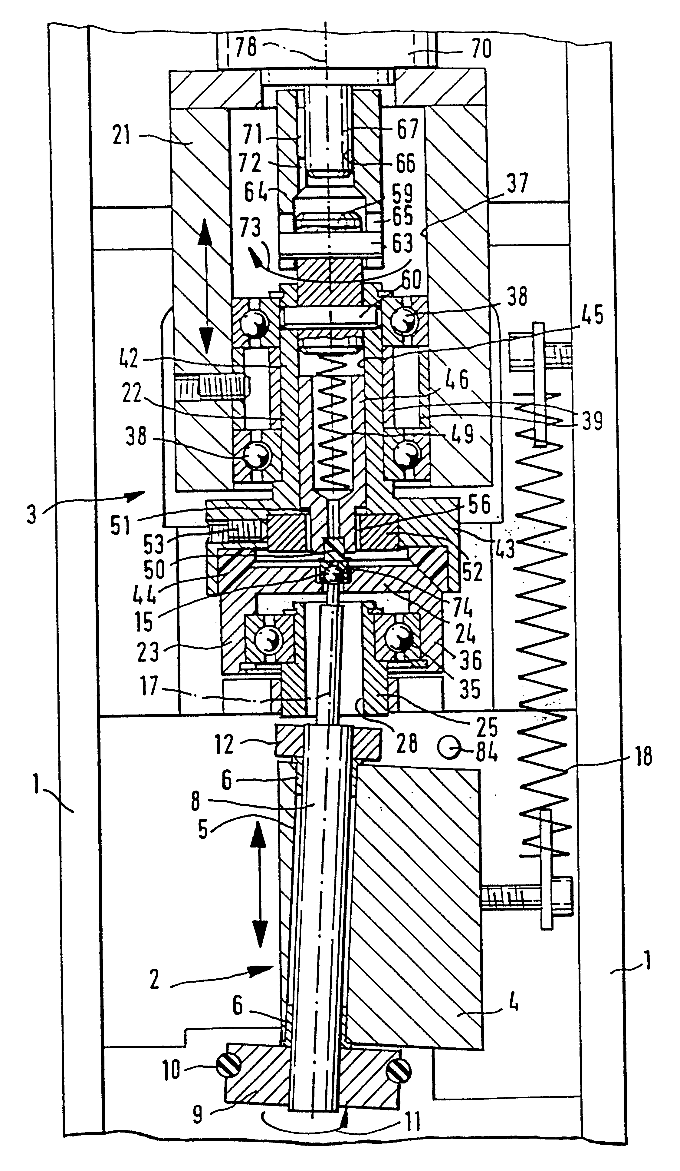
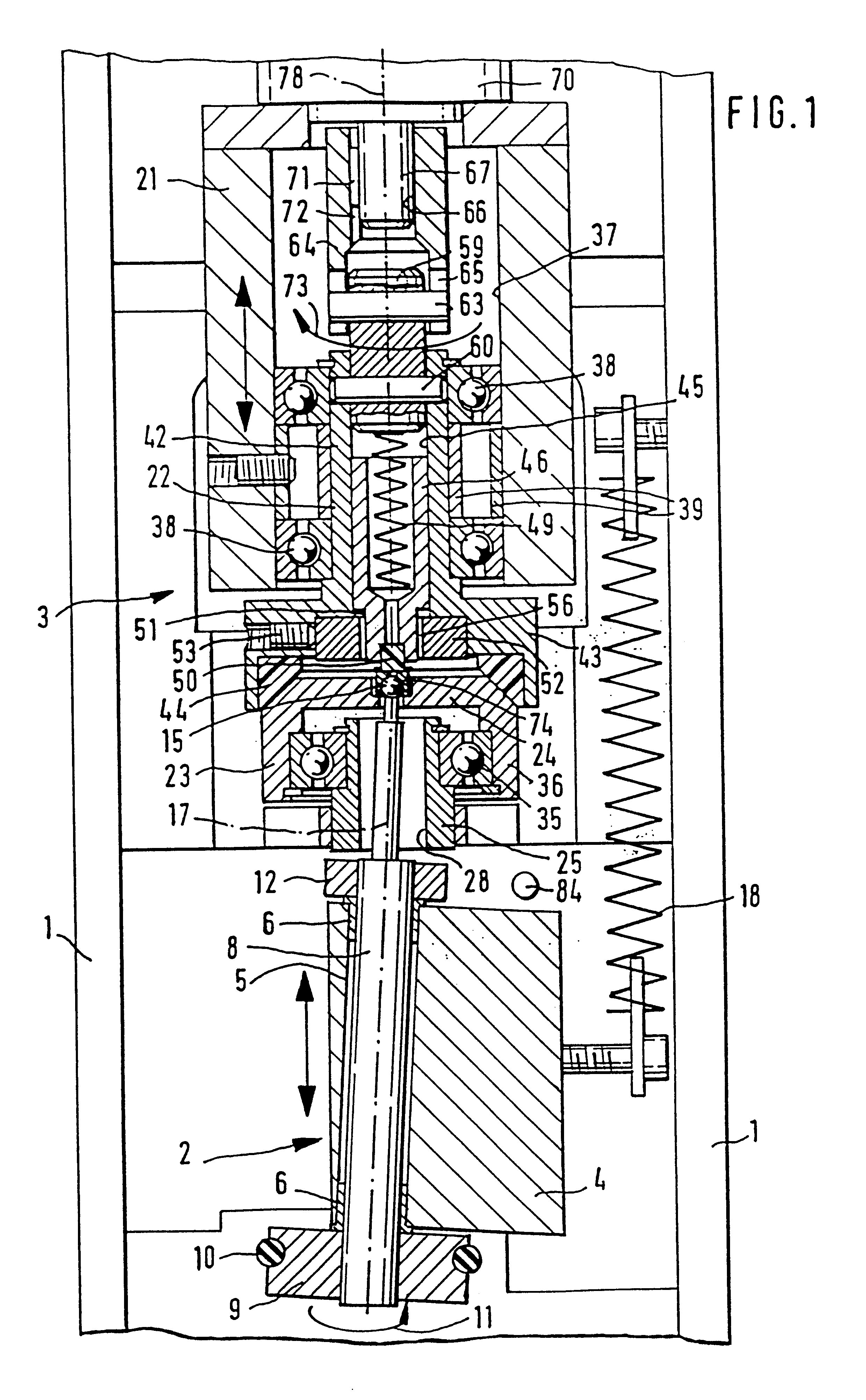
In FIG. 1, an apparatus according to the invention for producing rotationally symmetrical valve seat faces of high surface quality in valves is shown; it has an apparatus frame 1, on which a tool holder unit 2 and a valve seat body chucking unit 3 are supported. The tool holder unit 2 and valve seat body chucking unit 3 are axially displaceable in the direction of the longitudinal axis of the apparatus frame 1. The tool holder unit 2 has a bearing block 4, with a bearing bore 5 extending on an incline from the longitudinal axis of the apparatus frame 1, in which bore bearing bushes 6 are disposed that act as slide bearings for a tool receiving body 8, which extends, thus rotatably supported, through the bearing bore 5 of the bearing block 4. Connected to the tool receiving body 8 is a pulley 9, which is engaged by a drive belt 10 that rotates the tool receiving body 8 in the direction of the arrow 11. Instead of the belt drive, the tool receiving body 8 can also be driven directly o...


PUM

PropertyMeasurementUnit
Forceaaaaaaaaaa
Surfaceaaaaaaaaaa
Frequencyaaaaaaaaaa

Abstract

In known methods for producing rotationally symmetrical valve seat faces, the valve closing body is brought into contact with the valve seat face of the valve seat body, set into a rotary motion, and set parallel to the rotary axis into an oscillating motion of high frequency. When the valve is assembled, care must then be taken that this pairing of the valve closing body and the valve seat body is preserved. In the novel method, the valve seat body is inserted into a receiving body and fixed by means of a tappet. A spherical tool body engages the valve seat face of the valve seat body with a contact pressure force and rotates in a rotary direction that is opposite a rotary direction of the valve seat body. The valve seat body axis and the tool body rotary axis are inclined relative to one another, so that a lubricant introduced can constantly build up a film of lubricant between the tool body and the valve seat face, and an elastic deformation ensures in the valve seat face, producing a relatively broad smoothing trace without significant indentation. The method and the apparatus are especially well suited to machining valve seat faces of fuel injection valves for fuel injection systems of internal combustion engines.

Description

PRIOR ARTThe invention is based on a method and an apparatus for producing rotationally symmetrical valve seat faces of high surface quality in valves. A method and an apparatus for performing the method are already known (German Patent DE 39 25 043 C2), in which the movable valve part is put into contact with the valve seat face of the valve seat body and set into a rotary motion; an oscillating motion acting parallel to the axis of rotation is transmitted at high frequency to the valve seat body and the movable valve part. Although this produces surfaces with a very high surface quality that assures good tightness of the valve, nevertheless it is disadvantageous for the assembly of the valve that the individual pairings of the movable valve part and valve seat body that have been treated by the known method must be retained, which is a problem in terms of the sequence of assembly.ADVANTAGES OF THE INVENTIONThe method of the invention and the apparatus of the invention have the adv...

Claims


Application Information

Patent Timeline
IPC IPC(8): B24B39/00B24B39/02B23P9/00B23P9/02B24B15/02
CPCB23P9/02B24B39/02Y10T29/49895Y10T29/49409B24B1/04
Inventor HEROLD, STEFANKIRSTEN, OLIVER
Owner ROBERT BOSCH GMBH
Why Eureka
Eureka Blog
Learn More