Combined gas turbine power system using catalytic partial fuel oxidation

a technology of catalytic partial fuel oxidation and gas turbine power system, which is applied in the direction of combustion process, inorganic chemistry, air transportation, etc., can solve the problems of not allowing the (re)conversion of commercial gas turbines, for instance, implementing each of the aforementioned patents, etc., and achieves the prevention of local runaway reaction risk and appreciable reduction of the period of use.

Inactive Publication Date: 2001-02-20
KALITVENTZEFF BORIS +1
View PDF2 Cites 35 Cited by
  • Summary
  • Abstract
  • Description
  • Claims
  • Application Information

AI Technical Summary

Benefits of technology

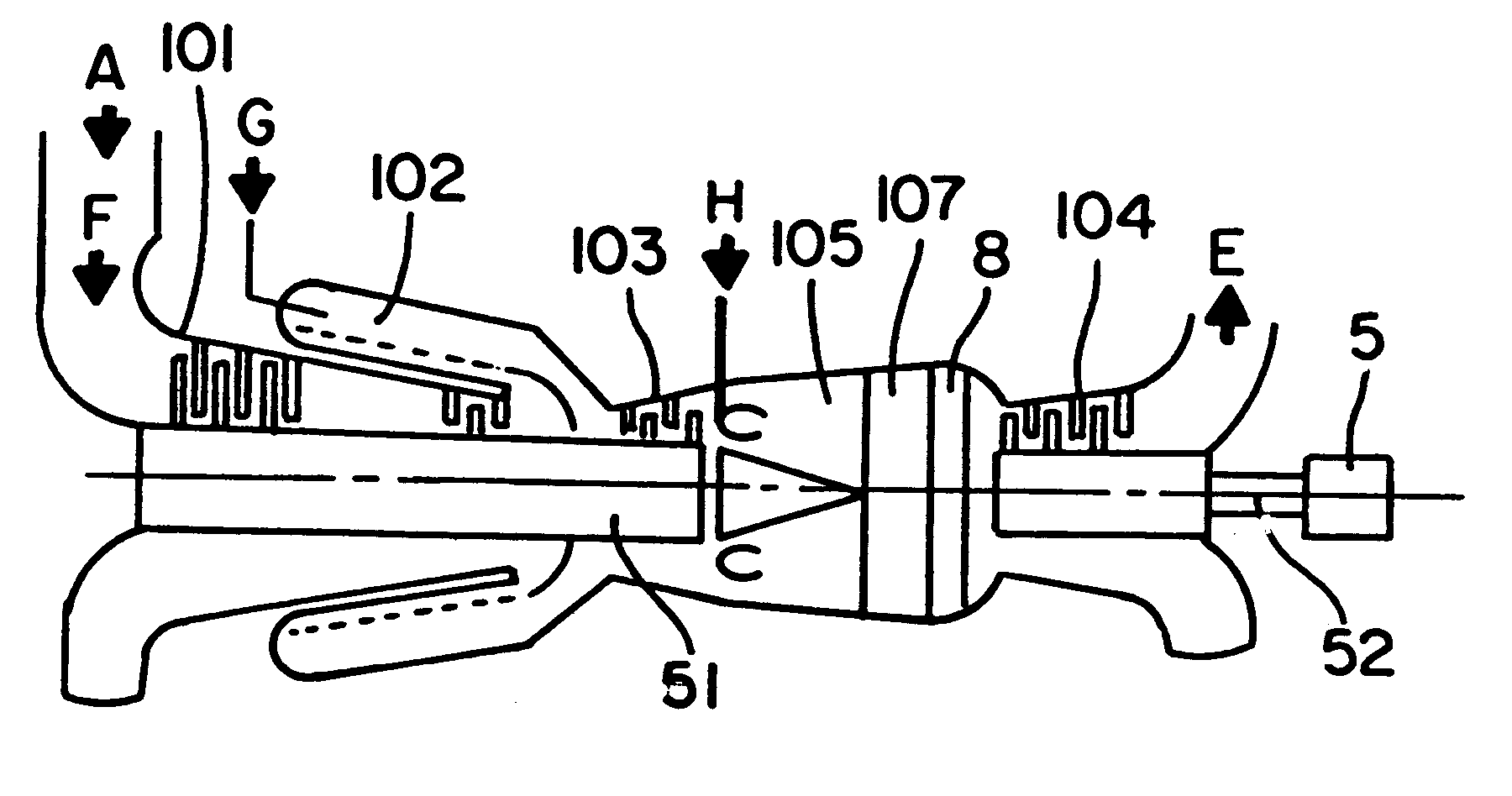
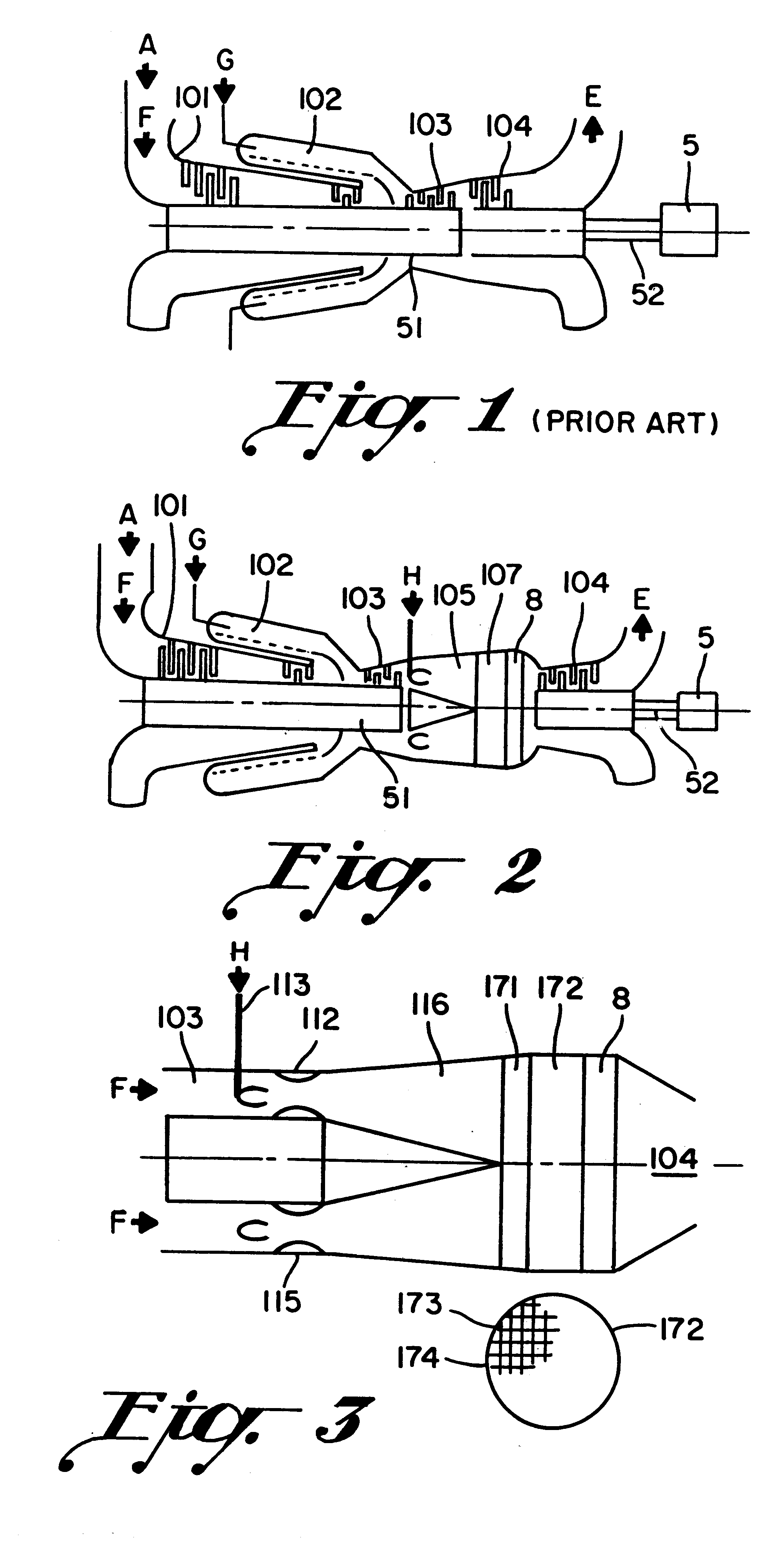
In accordance with this invention, the presence of a suitable quantity of an initiator, advantageously hydrogen, in the process flux at the inlet of the partial-oxidation reactor helps to solve the above problems. In addition, it provides a complementary degree of flexibility in respect of the control and operability of the entire system. This hydrogen comes from an external source if it is economically available on the site or from the system itself. In this case, there are two alternatives: either partial recycling of the gases collected downstream of the reactor or an innovative combination of a partial-oxidation gas turbine and a small so-called "reforming" reactor which exchanges heat indirectly with the effluent from the power turbine.
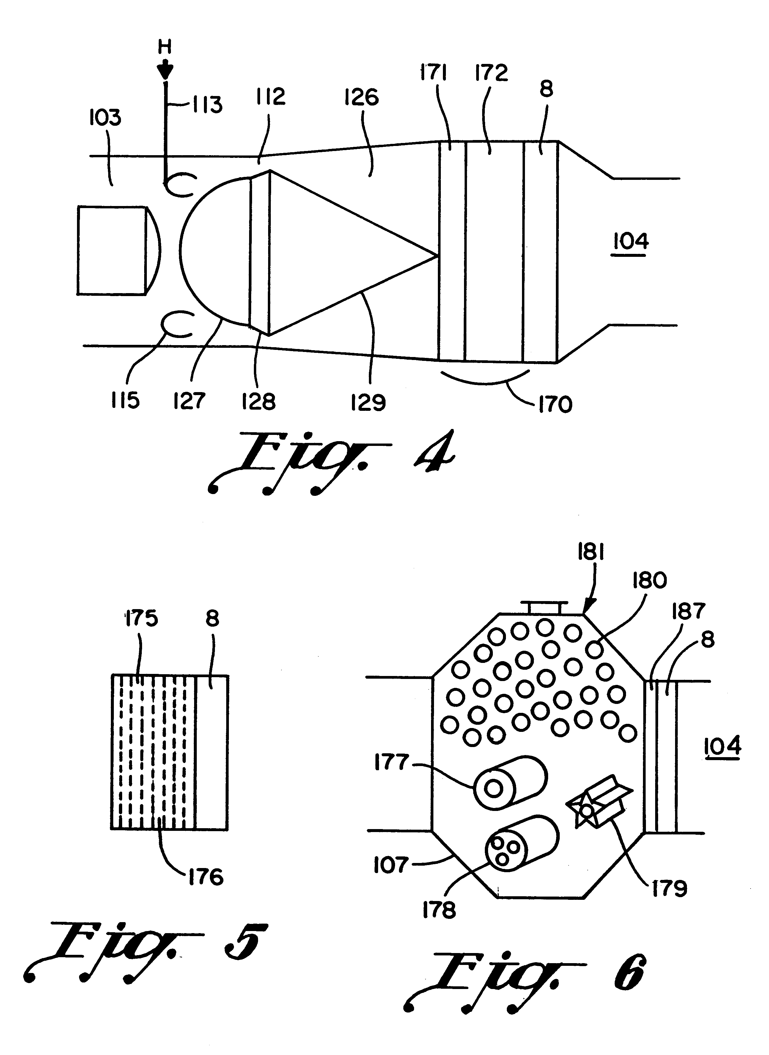
The reactions involved in the partial oxidation of a gaseous fuel take place at different rates, these being characterized by different activation energies. It follows that the temperature profiles are difficult to control and therefore that thermal stresses are difficult to avoid in the catalytic masses, the period of use of which will be appreciably reduced. The catalysts are in this case rendered friable, just as they could be by deposition of carbon within the pores of the catalyst. This additional problem. Thus, by using successive layers of catalysts of different type and / or different activity, the temperature profiles are fully controlled and the risk of local runaway of the reactions is prevented.

Problems solved by technology

The systems briefly described in the aforementioned Patents BE-769,133 and BE-1,003,760 have a major drawback as they do not allow the available commercial gas turbines to be (re) converted.
Thus, in general, problems of, for instance, implementing each of the aforementioned patents remain.

Method used


Image

  • Combined gas turbine power system using catalytic partial fuel oxidation
  • Combined gas turbine power system using catalytic partial fuel oxidation
  • Combined gas turbine power system using catalytic partial fuel oxidation

Examples


example 1

silo 212, as illustrated in FIGS. 11 and 12, replacing, according to the invention, that illustrated in FIG. 10. In this case, it is preferred to use a reactor 217 in the form of two reversed cones, containing catalyst in the form of a honeycomb held in place by meshes, as illustrated in FIG. 11. These reactors 217 also contain a peripheral booster-ejector 206, in FIG. 9, and a toroidal injector 215 supplied with pressurized gas.

Another form of vertical reactor 227 is shown in FIG. 12 and comprises a peripheral compressed-air supply, a mixer-ejector 226 and a layer of partial-oxidation catalyst 272 as used in chemistry for secondary reforming. In this case, a flame 230 is produced at the outlet of the ejector 226.

example 2

of cylindrical combustors placed obliquely all around the gas turbine illustrated in FIG. 13. The combustors are replaced by catalytic partial-oxidation reactors 237 as shown in FIGS. 13-15 and they include a peripheral compressed-air supply. The booster-ejector devices supply non-inflamed mixture to the catalytic masses 273, in the form of a honeycomb, as in FIG. 14, or according to the loose reforming catalyst 274, as illustrated in FIG. 15.

After leaving the catalyst 272, the gases pass through a high-temperature filter 8 or 208 intended to collect accidentally emitted particles.

The precise dimensions of the reactor 207 according to FIG. 8 are determined by the characteristics of the gas turbine which is to be converted to partial oxidation.

The reaction gas produced at the defined temperature passes through the expansion turbine 203, generating mechanical energy in greatly increased quantity compared to the initial situation.

The air compressor of a conventional gas turbine outputs...


PUM


Abstract

A gas turbine power system for generating energy by means of a gas turbine cycle, wherein heat energy is more effectively used by burning the exhaust gases (109) and the partial oxidation of said exhaust gases (109) is achieved by means of a hypostoichiometric amount of air and steam fed into a catalytic reactor (107) to form a first oxidation stage followed downstream in said turbine (103) by additional oxidation occurring in a power turbine (104) or downstream therefrom, said power turbine being in turn arranged downstream from the catalytic reactor (107). Catalytic partial oxidation may be performed using a supply of an initiating agent, particularly hydrogen. The method is remarkable in that the hydrogen fed into the reactor inlet through an injector (113) is provided by recycling part of the effluent from the reactor, the power turbine or a reforming reactor for reforming part of the fuel gas with a large excess amount of steam for performing catalytic partial oxidation.

Description

The present invention relates to a thermal energy system comprising at least one gas turbine intended to generate mechanical and / or electrical energy by operating a gas-turbine cycle in which exhaust gases of the cycle having a certain amount of energy capable of beneficiation, in particular mechanical and / or thermal beneficiation, are produced.TECHNOLOGICAL BACKGROUNDThe use of conventional gas turbines for the proposed industrial applications is well known. Thus, when a cycle comprising one or more gas turbines is placed upstream of an existing steam cycle of a power station, the overall energy efficiency of a conventional power station may go from 0.4 to 0.45 at the cost of extensive modification of the steam cycle, in particular by the addition of economizer exchangers. However, this technique proves to be expensive and only justifiable if the cost of the fuel itself is high. What is more, this technique involves an appreciable reduction in the useful power of the steam cycle. T...

Claims


Application Information

Patent Timeline
Patent Type & Authority Patents(United States)
IPC IPC(8): F02C3/00F01K21/04F01K21/00F02C3/32F02C6/00F02C3/30F02C3/20F23R3/40F23R3/00F23C13/00
CPCF01K21/047F02C3/32F02C6/003F23R3/40C01B3/363F02C3/305C01B2203/84F23R2900/00002F23R2900/03342Y02E20/14Y02T50/67Y02T50/671C01B2203/0244C01B2203/0261C01B2203/1023C01B2203/1058C01B2203/107C01B2203/1082C01B2203/148Y02P20/129Y02T50/60
Inventor KALITVENTZEFF, BORISRIBESSE, JACQUES
Owner KALITVENTZEFF BORIS
Why Eureka
Try Eureka