Compact low phase error antenna for the global positioning system

a global positioning system, low phase error technology, applied in the structure of resonant antennas, non-resonant long antennas, radiating elements, etc., can solve the problems of large backlobe, multipath errors, and prone to phase and multipath errors

Inactive Publication Date: 2001-03-13
MICROPULSE INCORPORATED
View PDF6 Cites 11 Cited by
  • Summary
  • Abstract
  • Description
  • Claims
  • Application Information

AI Technical Summary

Problems solved by technology

Often, the phase center of the antenna does not correspond the physical center of the antenna due to multipath errors and/or phase errors.
Typical GPS antennas are either dual frequency patch antennas or cross dipole antennas which are particularly prone to phase and multipath errors.
Multipath errors occur when signals transmitted from the GPS satellites reflect off hills or objects and combine.
An antenna with such a receive pattern is said to have a large backlobe and is more susceptible to multipath problems.
Phase errors are inherent in certain antenna element designs such as patch antenna designs.
Other phase errors occur due to manufacturing t

Method used


Image

  • Compact low phase error antenna for the global positioning system
  • Compact low phase error antenna for the global positioning system
  • Compact low phase error antenna for the global positioning system

Examples


Embodiment Construction

While the present invention is described herein with reference to illustrative embodiments for particular applications, it should be understood that the invention is not limited thereto. Those having ordinary skill in the art and access to the teachings provided herein will recognize additional modifications, applications, and embodiments within the scope thereof and additional fields in which the present invention would be of significant utility.

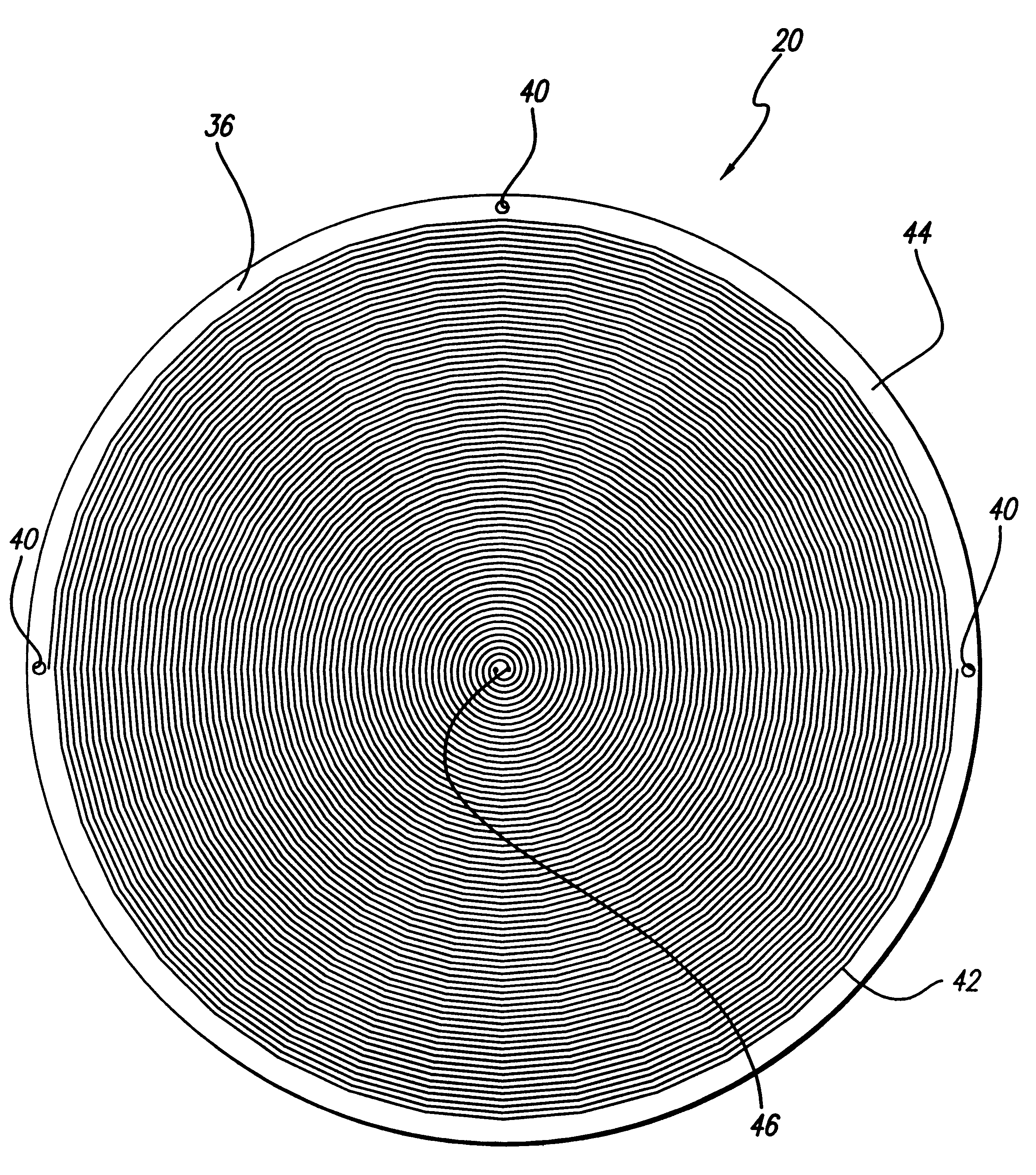
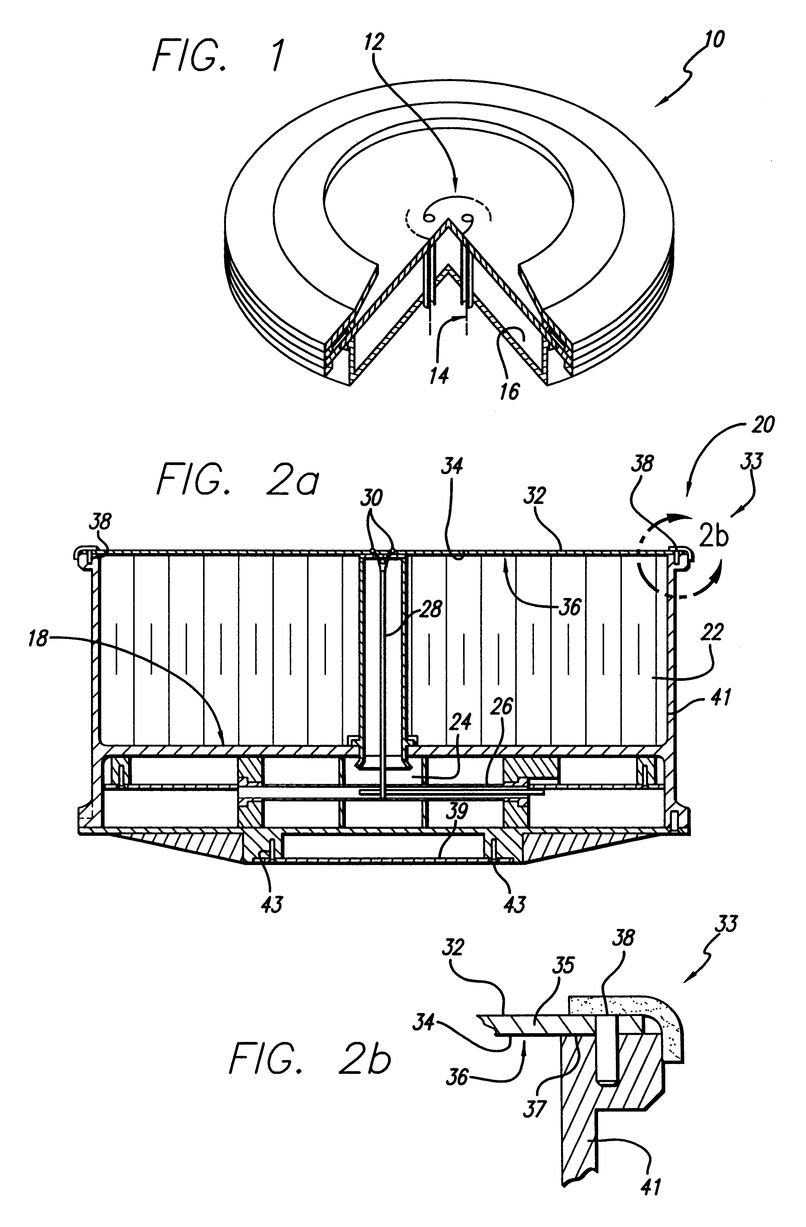
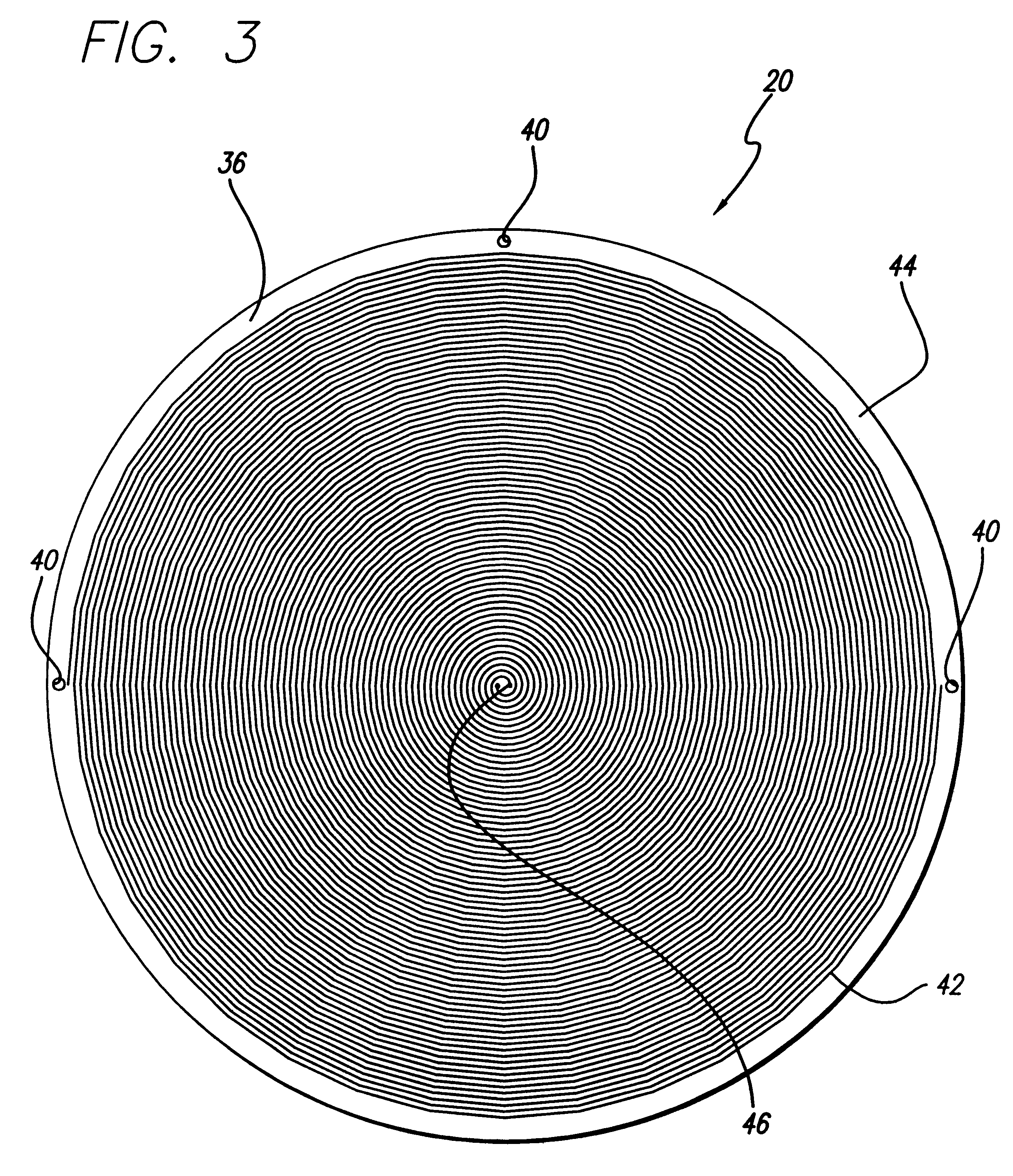
FIG. 1 is a cut-away diagram of an antenna 10 constructed in accordance with the teachings of the present invention. The antenna 10 is constructed of aluminum or other suitable material. The antenna 10 has antenna elements or spiral arms 12. The spiral arms 12 are fed by a conventional balun 14 having minimum squint. Minimum squint baluns help contribute to a desirable symmetric radiation pattern that does not lean to one side or the other.

In transmit mode, the spiral arms 12 radiate electromagnetic energy communicated to the arms 12 via ba...


PUM


Abstract

A low phase error antenna. The antenna is adapted for use with the Global Positioning System and includes a spiral antenna for receiving electromagnetic energy at a first standard frequency (L1) and a second standard frequency (L2). The spiral antenna has a spiral element with a circumference greater than approximately one and a half times the wavelength of electromagnetic energy at the lowest frequency (L2). The cavity of the antenna is unloaded and includes a balun adjusted for zero squint. The antenna element is either a logarithmic spiral or an archimedian spiral. In the illustrative embodiment, the spiral antenna includes a cavity having a depth which varies in accordance with the received electromagnetic energy. The cavity is approximately ¼ of a wavelength deep at the positions along spiral that receive electromagnetic energy.

Description

1. Field of InventionThis invention relates to the Global Positioning System (GPS). Specifically, the present invention relates to low phase error antennas for receiving GPS signals.2. Description of the Related ArtThe Global Positioning System is used in a variety of demanding applications ranging from geological surveys, to military positioning applications. Such applications require accurate antennas to precisely determine distances and positions with sub-millimeter accuracy.The Global Positioning System includes a constellation of satellites equipped with GPS transmitters. A ground receiver receives signals from the satellites. By measuring signal travel time from the satellites to the phase center of the ground receiver's antenna, the position of the ground receiver may be determined. The phase center of the antenna corresponds to the point at which the antenna appears to receive a spherical wavefront. The phase center may be different than the physical center of the antenna.Of...

Claims


Application Information

Patent Timeline
IPC IPC(8): H01Q9/04H01Q1/36H01Q9/27H01Q1/38
CPCH01Q1/36H01Q1/38H01Q9/27
Inventor OW, STEVEN G.CONNOLLY, PETER J.
Owner MICROPULSE INCORPORATED
Why Eureka
Try Eureka