
Developer-carrying member, and developing device and image forming apparatus including the member

a technology of developing device and image forming apparatus, which is applied in the direction of electrographic process apparatus, shafts and bearings, instruments, etc., can solve the problems of reducing product yield, affecting the quality of developing device, and posing a serious obstacle to providing high-quality toner images

Inactive Publication Date: 2001-03-13
CANON KK +1
View PDF11 Cites 25 Cited by
  • Summary
  • Abstract
  • Description
  • Claims
  • Application Information

AI Technical Summary

Benefits of technology

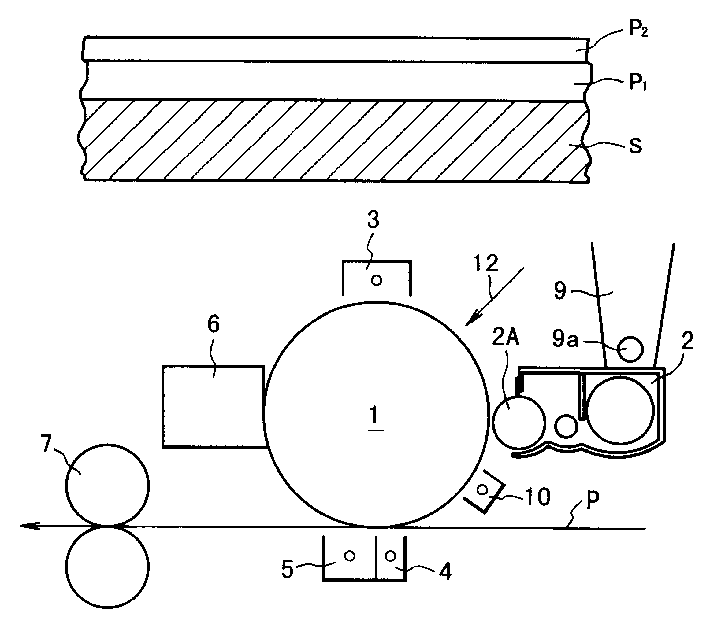
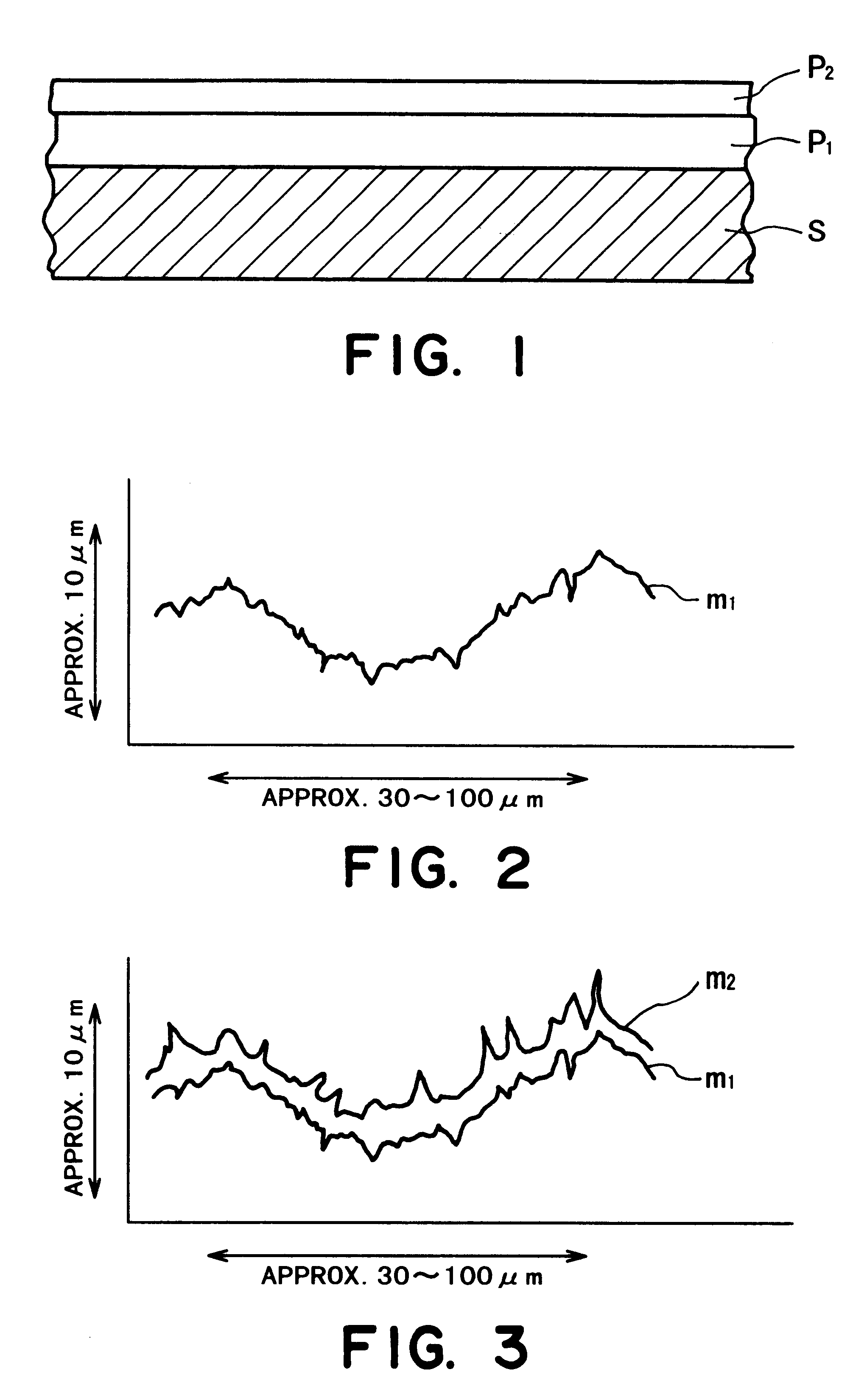
In the developer-carrying member according to the present invention, an electroless plating layer is disposed as an intermediate layer between a substrate and an electroplating layer, whereby the electroplating layer exhibiting a high hardness can be formed with a high accuracy of surface roughness free from abnormal metal deposition sites. More specifically, in the electroless plating, a metal is deposited on the substrate by a chemical reaction, so that the metal deposition is not concentratively caused at minute projections or along edges of cracks present on the substrate surface. As a result, the shapes of such projections and cracks on the substrate surface are not copied or reflected on the surface of the intermediate electroless plating layer surface, so that the electroplating layer thereon are free from adverse influences of the projections and cracks on the substrate surface.

Problems solved by technology

Such a heat treatment can substantially lower the product yield.
This is because the substrate can cause a thermal deformation on the order of several tens of .mu.m in a direction perpendicular to its longitudinal direction as a result of the heat treatment, so that the spacing between the electrostatic image-bearing member and the developer-carrying member fluctuates locally, thereby causing local toner image irregularity.
Such an image irregularity poses a serious obstacle for providing high-quality toner images.
However, the use of an electroplating layer is accompanied with a problem for the purpose of providing a surface-coating layer having a prescribed desirable surface shape.
It is difficult to provide an electroplating layer with such a prescribed surface roughness.
However, the substrate surface is generally accompanied with minute projections and cracks, and the electric lines of force tend to concentrate onto peaks of the projections or edges of the cracks.
As a result, the metal is abnormally or excessively deposited at these sites, thus failing to provide an electroplating layer with prescribed surface roughness.

Method used


Image

  • Developer-carrying member, and developing device and image forming apparatus including the member
  • Developer-carrying member, and developing device and image forming apparatus including the member
  • Developer-carrying member, and developing device and image forming apparatus including the member

Examples


production example 1

(Blasting)

An Al sleeve of 32 mm in outer diameter and 0.65 mm in thickness was subjected to surface-blasting with 600 mesh-spherical glass beads in the following manner.

More specifically, against the sleeve rotating at 36 rpm, the glass beads were blown through 4 nozzles of each 7 mm in diameter and disposed at a distance of 150 mm in 4 directions around the sleeve at a blasting pressure of 2.5 kg / cm.sup.2 for 9 sec. (totally: 36 sec). After the blasting, the blasted sleeve surface was washed and dried to have surface roughnesses Ra of 0.6 .mu.m and Rz of 4 .mu.m.

(Plating pre-treatment)

The blasted Al sleeve was treated with a commercially available zincate agent ("SUMER K-102", available from Nippon Kanizen K.K.) to surface-deposit zinc thereon for improving the adhesion of a N--P plating layer to be formed on the Al sleeve surface.

(Ni--P plating)

The above-treated Al sleeve was dipped in a commercially available Ni--P electroless plating liquid ("S-754", available from Nippon Kamize...

production example 2

An identical Al sleeve as used in Production Example was subjected to the following treatments to prepare Developing sleeve 2.

(Blasting)

Blasting was performed in the same manner as in Production Example 1 except for using 400 mesh-spherical glass beads instead of the 600 mesh-glass beads. The blasted sleeve exhibited Ra=0.8 .mu.m and Rz=5 .mu.m.

(Plating-pretreatment)

Performed similarly as in Production

example 1

(Ni--B plating)

The above-treated Al sleeve was dipped in an Ni--B electroless plating liquid (a weakly acidic solution of nickel sulfate, dimethylamineborane and sodium malonate) for electroless plating to form a 17 .mu.m-thick Ni--B (B content=60 wt. %) plating layer.

The thus Ni--B-plated Al sleeve exhibited Hv=550-700, Ra=0.6 .mu.m, Rz=4 .mu.m, a coercive force=90 oersted, and a saturation magnetic flux=350 Gauss, thus exhibiting magnetism as a whole.

(Ni plating)

The Ni--B-plated sleeve was subjected to Ni-plating in the same manner as in Production Example 1.

(Cr plating)

The Ni-plated sleeve was subjected to Cr plating in the same manner as in Production Example 1. The Cr-plated sleeve exhibited a coercive force=83 oersted and a saturation magnetic flux=5850 Gauss, thus exhibiting ferromagnetism as a whole.

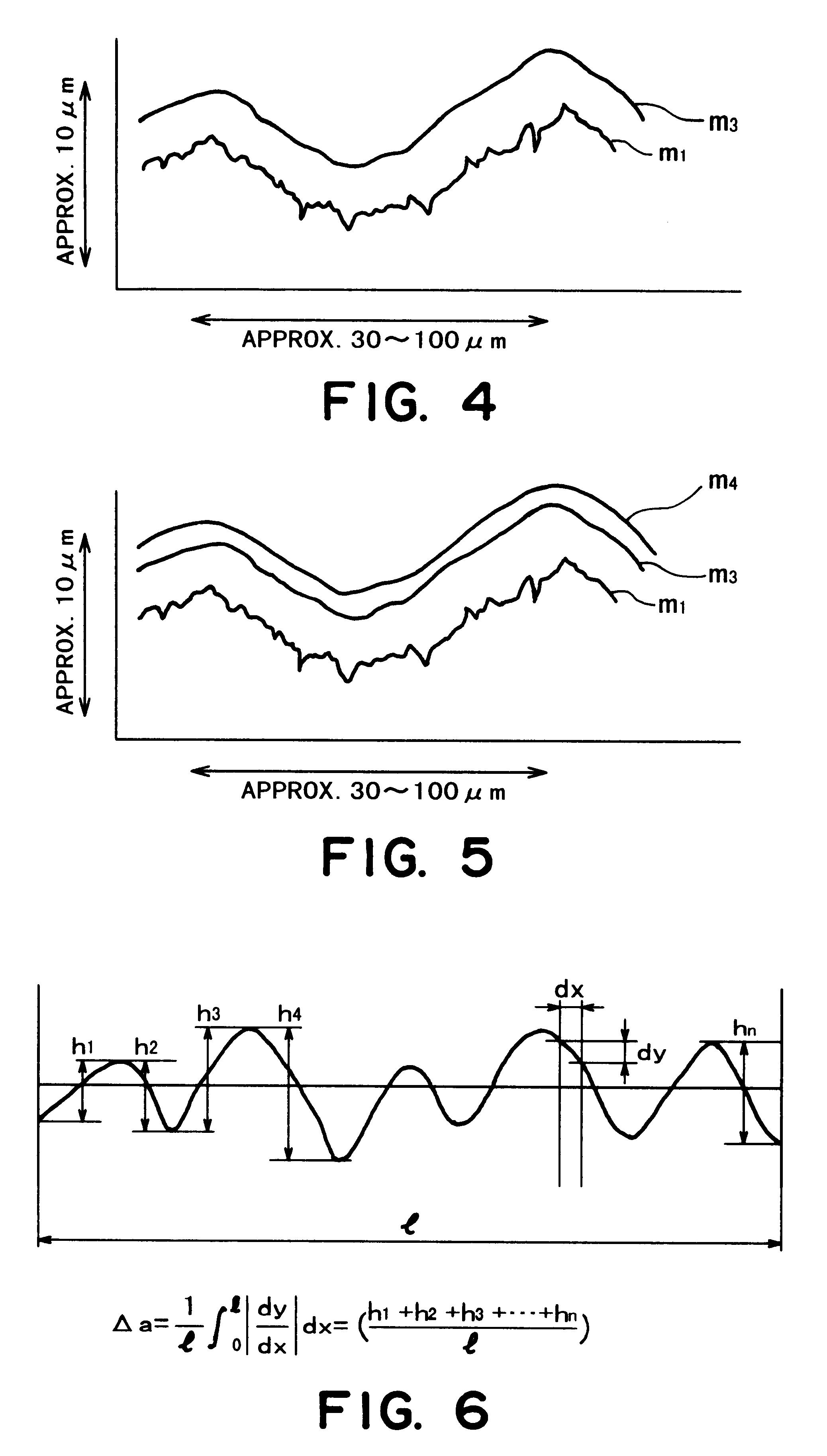
The Cr-plated sleeve also showed Hv=605-640, Ra=0.7 .mu.m, Rz=4.3 .mu.m and .DELTA.a=0.08.

(magnet insertion)

Developing sleeve 2 was completed by inserting an identical magnet as ...


PUM

PropertyMeasurementUnit
Thicknessaaaaaaaaaa
Magnetic fieldaaaaaaaaaa
Electrical resistanceaaaaaaaaaa

Abstract

A developer-carrying member to be installed in an electrophotographic developing device for carrying and conveying a developer along a surface thereof, is formed of a substrate, and an intermediate electroless plating layer and an electroplating layer disposed in this order on the substrate. As a result of the electroless and electro double plating layer structure, the developer-carrying member is provided with a wear-resistant surface which has an appropriate degree of roughness suitable for conveying the developer thereon and is yet free from minute projections and cracks undesirable from the viewpoint of continuous image forming performances.

Description

FIELD OF THE INVENTION AND RELATED ARTThe present invention relates to a developer-carrying member, a developing device and an image forming apparatus used for electrophotographic copying machines, laser beam printers, facsimile apparatus, printing apparatus, etc.Conventional developer-carrying members are provided with roughened uneven surfaces for conveying a developer. As old proposals, Japanese Laid-Open Patent Application (JP-A) 54-79043 disclosed are provided with knurls principally for a two-component developer system and JP-A 55-26526 proposed one provided with a roughened surface principally for a mono-component developer system.As a material for such a surface-roughness developer-carrying member, it has been proposed to use a relatively hard material for forming a surface-coating layer on a substrate. For example, JP-A 58-132768 has disclosed a developer-carrying member comprising an aluminum substrate surface-coated with a nitride such as TiN or CrN, a carbide such as TiC...

Claims


Application Information

Patent Timeline
IPC IPC(8): G03G15/09G03G15/08C25D7/00F16C13/00
CPCG03G15/0818G03G15/0928G03G2215/0861
Inventor HONDA, TAKAOHARA, NOBUAKITAJIMA, HATSUOWATANABE, TSUYOSHIYAMASHITA, KEITAROKASHIWAGI, HIROMI
Owner CANON KK
Learn More