Optical module, method for manufacturing optical module and optical communication apparatus

a manufacturing method and technology for optical modules, applied in the field of optical modules, can solve the problems of reducing the reliability of plastic packages, high moisture permeability, and large thermal expansion coefficients, and achieve the effect of reducing the molding cost of resin case type packages and ensuring the reliability of optical modules

Inactive Publication Date: 2001-04-24
OCLARO JAPAN INC
View PDF13 Cites 81 Cited by
  • Summary
  • Abstract
  • Description
  • Claims
  • Application Information

AI Technical Summary

Benefits of technology

A first object of the present invention is to secure the reliability of ...

Problems solved by technology

The plastic package is influential for lowering the cost of the optical module as compared with the metallized package or the ceramic package, but has difficulties such that generally, the moisture permeability is high, and the coefficient of thermal expansion is large.
These factors synthetically lower the reliability of the plastic package.
In particular, in the semiconductor laser module, a demand relative to such a position is severe.
Any of the aforementioned prior arts have both merits and demerits with respect to such demands as noted above, and fail to respond to the demands of the current industrial world.
Considering the dimensional accuracy of the receptacle itself and the deformation of the receptacle caused by the insert- and pull force of connector and the thermal expansion, the module in Article 2 can be applied to a light emitting diode having a large pot size but is not suitable for a laser diode having a mall spot size.
Accordingly, the thermal stress and the external force are concentrated on the interface between the bare fiber portion and the jacket portion to bring forth a problem in that the bare fiber is broken.
There is a difficulty ...

Method used


Image

  • Optical module, method for manufacturing optical module and optical communication apparatus
  • Optical module, method for manufacturing optical module and optical communication apparatus
  • Optical module, method for manufacturing optical module and optical communication apparatus

Examples


first embodiment

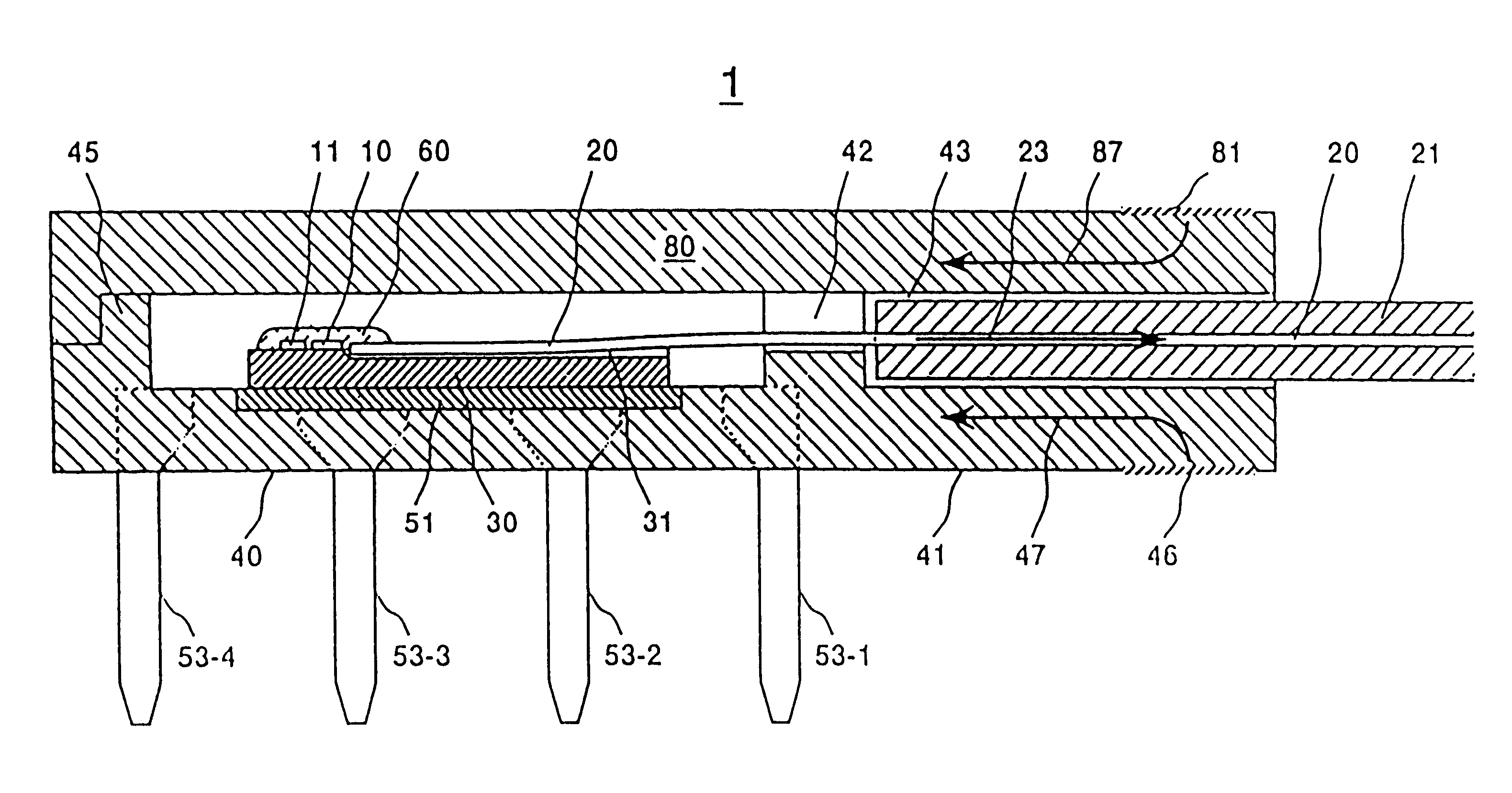
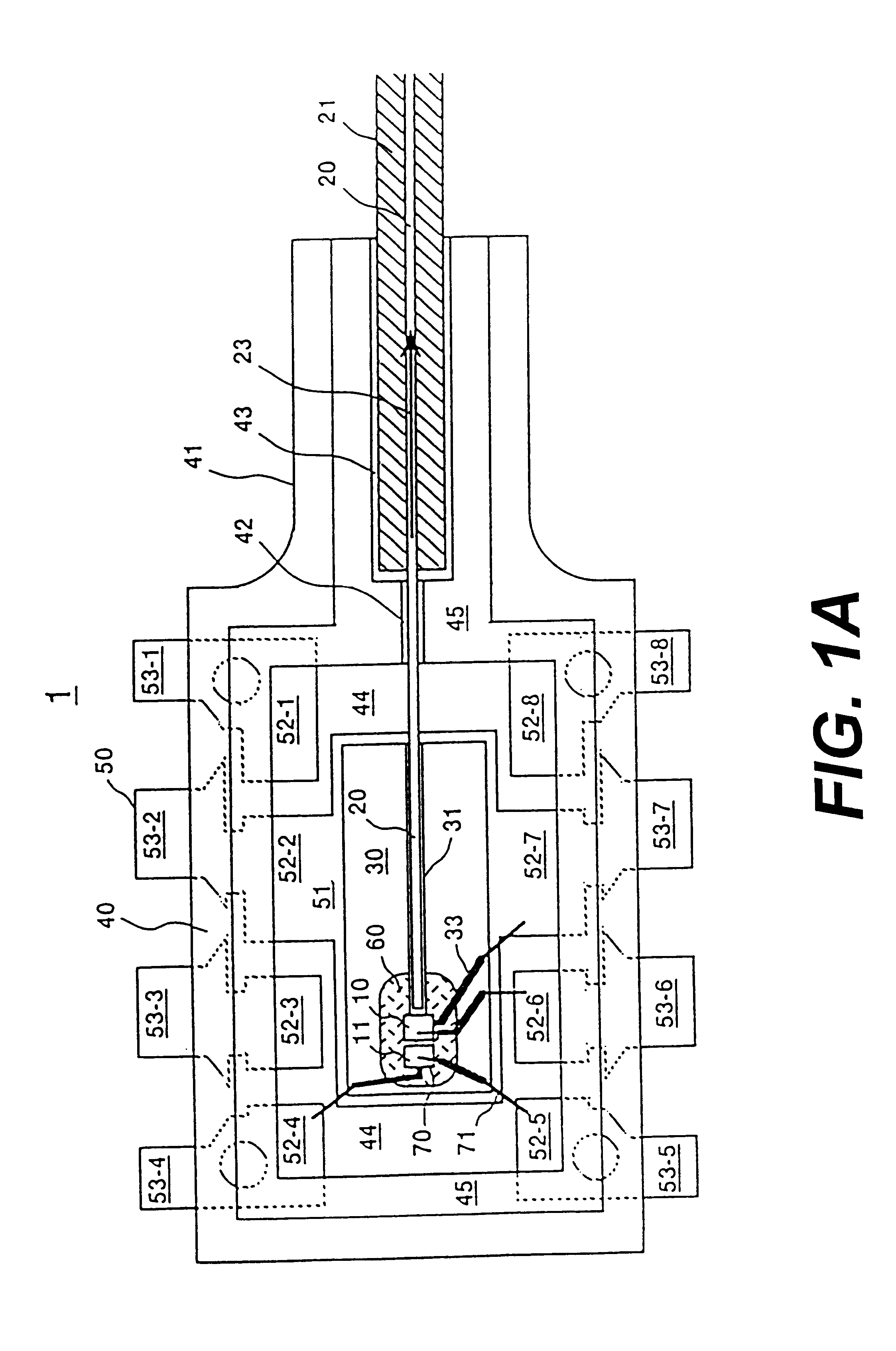
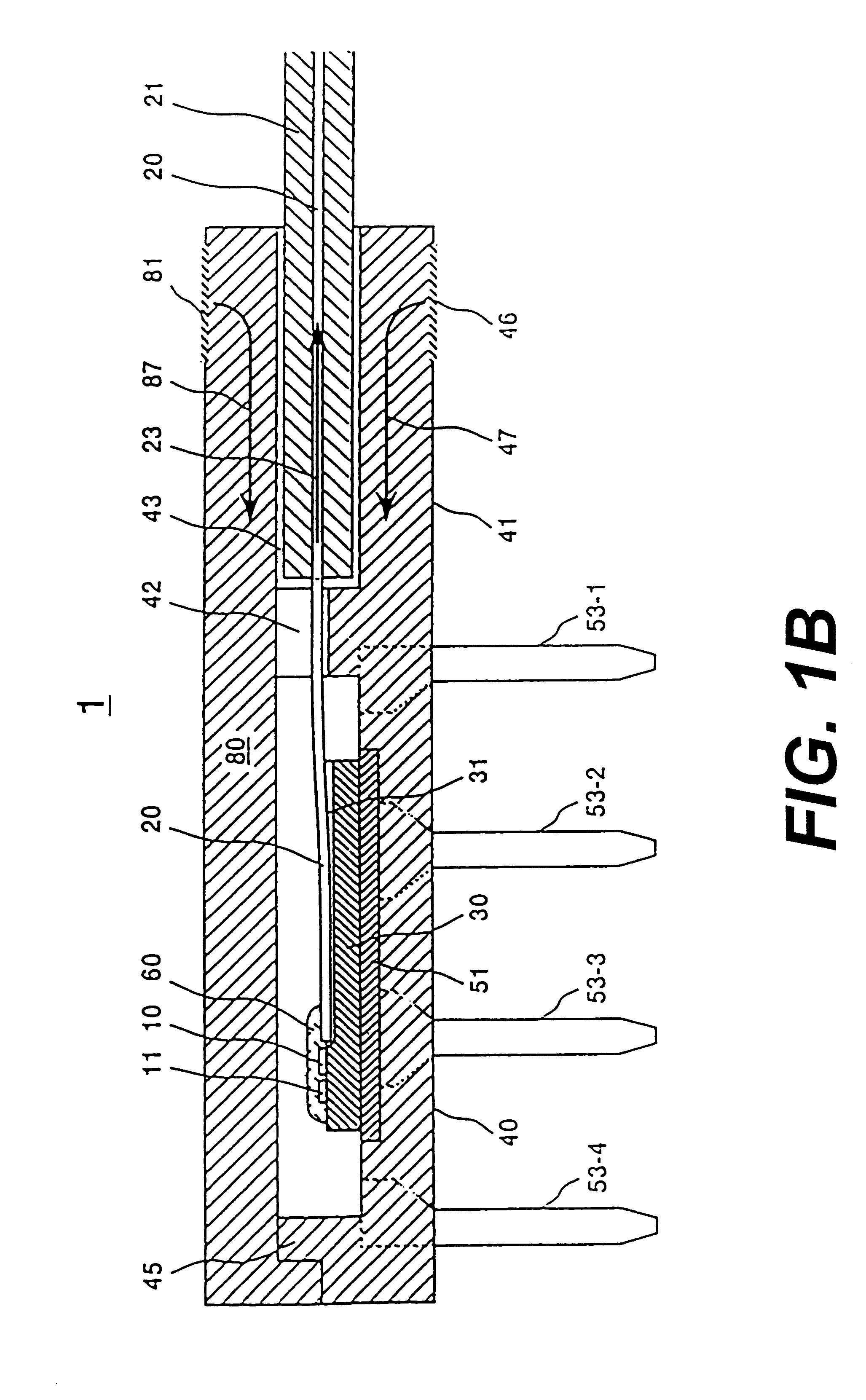
The first embodiment according to the present invention will be explained in detail with reference to the drawings. FIGS. 1A, 1B and 1C are respectively views of assistance in explaining the optical module according to the present invention. These drawings show the pigtail type optical transmission module for the resin case type package. FIG. 1A is a partial plan view as viewed from the top, FIG. 1B is a partial sectional view as viewed from the side, and FIG. 1C is a sectional view in the direction crossing with the optical axis of the optical fiber.

As shown in FIGS. 1A, 1B and 1C, the resin case type plastic package receives therein optical devices 10, 11, a bare fiber 20 at the extreme end of the pigtail type optical fiber, and a substrate 30 for mounting members such as the optical devices. These members are sealed within a cavity 44. The cavity 44 is formed mainly by a base 40 and a cap 80. A lead frame 50 is formed integrally with a resin case type plastic package 40.

The optic...

embodiment 2

The second embodiment provides an example of the above-described "Comprehensive molding type package", more specifically, an example of a pigtail type optical transmission module by way of a comprehensive molding type package. Its main characteristic lies in that when a package is molded, the flowing direction of an epoxy resin is parallel with an optical axis direction of a fiber. Accordingly, since the flowing pressure of resin is not applied at vertically to the side of the fiber or jacket, the fiber or the jacket is not distorted at sideways, and molding is not made in the state where the alignment of the optical device and the fiber is deviated. Note that in this example, as the sealing method for the optical device and the fiber, a dropping method using a low elastic resin is used.

FIGS. 2A and 2B are respectively views of assistance in explaining the optical module according to the second embodiment. The present example shows a pigtail type optical transmission module by way o...

embodiment 3

In the third embodiment, as a packaging method, a transfer molding method which is a comprehensive molding mold is employed. As a sealing method for an optical device and a fiber, a dropping method is employed. In transfer molding of a package, with respect to the flowing of resins from the gate portion, care is taken so that the flowing direction is parallel with the optical axis direction of the fiber. Thereby, the ferrule is prevented from being deviated in position due to the molding pressure to secure the processing accuracy of a receptacle portion (i.e., accuracy of connection with a connector).

The third embodiment of the present invention will be described hereinafter with reference to FIGS. 3A and 3B. FIG. 3A is a partial plan view as viewed from the top, and FIG. 3B is a partial sectional view as viewed from the side. FIGS. 3A and 3B show a receptacle type optical transmission module by way of a package formed by a comprehensive molding method.

As shown in FIGS. 3A and 3B, a...


PUM


Abstract

An optical module for an optical device and an optical fiber is constituted by a pre-molded plastic package. In forming the plastic package, the main flowing direction of the molding resin is substantially parallel with the optical axis of the optical fiber. The optical module is formed by molding the resin by an injection method using pressure and then solidifying the resin. When the plastic package is formed by comprehensive molding, the flowing direction of the resin is parallel with the optical axis direction of the optical fiber to be installed in the optical module. As a result, for comprehensive molding, the molding pressure applied to the optical fiber is reduced. By using the resin case that is formed, the resulting package exhibits high rigidity and low thermal expansion properties in connection with the flowing direction of the resin, thus reducing the external stress and thermal stress applied to the optical fiber.

Description

The present invention relates to a resin molding type optical module having an optical device and an optical fiber packaged with a resin, an optical fiber communication apparatus using the resin molding type optical module, and an optical communication system.Recently, great demands for lowering the cost of the optical module have been made in order to introduce the optical fiber communication system into the subscriber network system on a full scale. From a viewpoint of this, with respect to the packaging technology, a resin sealing method (a plastic package method) is influential in place of a hermetic sealing method for a metallized package or a ceramic package which has heretofore occupied the mainstream in the field of optical devices. This is because the resin sealing method is suitable for mass- and inexpensive production.In the past, in the field of general semiconductor devices such as LSI and hybrid IC, the following various methods have been known as resin sealing methods...

Claims


Application Information

Patent Timeline
IPC IPC(8): G02B6/38G02B6/42G02B6/36
CPCG02B6/3865G02B6/4204G02B6/421G02B6/4292G02B6/3873H01L24/45H01L2224/45144H01L2924/19107H01L2924/00014H01L2924/12042H01L2924/12041H01L2924/12043H01L2924/14H01L2924/181H01L2924/00
Inventor KATO, TAKESHIYOSHIDA, KOJIHIRATAKA, TOSHINORIISHII, TOSHIAKIFUKUDA, KAZUYUKIISHIKAWA, TADAAKIMIURA, TOSHIMASAKONO, TSUTOMUTATSUNO, KIMIO
Owner OCLARO JAPAN INC
Why Eureka
Try Eureka