Synchronous multiplexed near zero overhead architecture for vacuum processes

a vacuum process and overhead architecture technology, applied in conveyor parts, transportation and packaging, coatings, etc., can solve the problems of consuming enormous power, difficult control, difficult to ignite, etc., and achieve the effect of increasing system cost and improving overall machine throughput and utilization

Inactive Publication Date: 2001-05-08
LAM RES CORP
View PDF24 Cites 59 Cited by
  • Summary
  • Abstract
  • Description
  • Claims
  • Application Information

AI Technical Summary

Benefits of technology

Some of the many advantages of the present invention are:
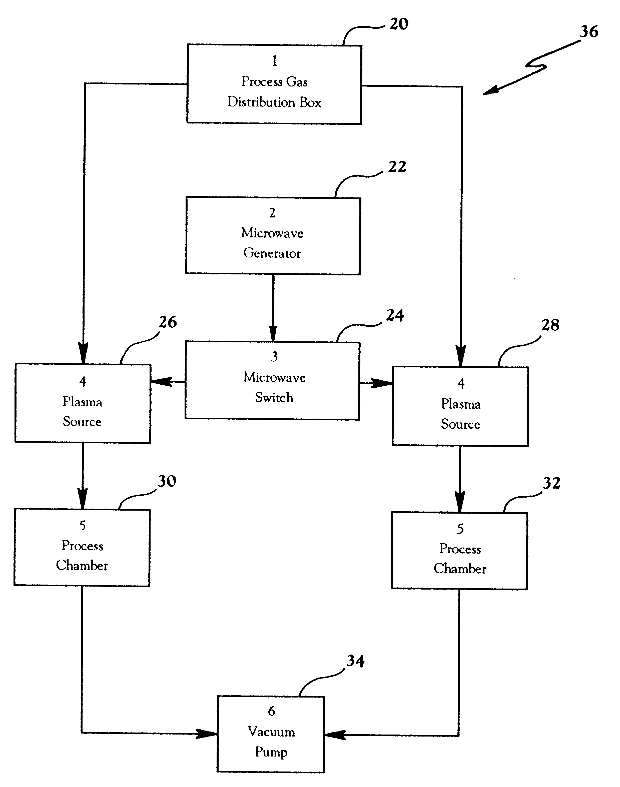
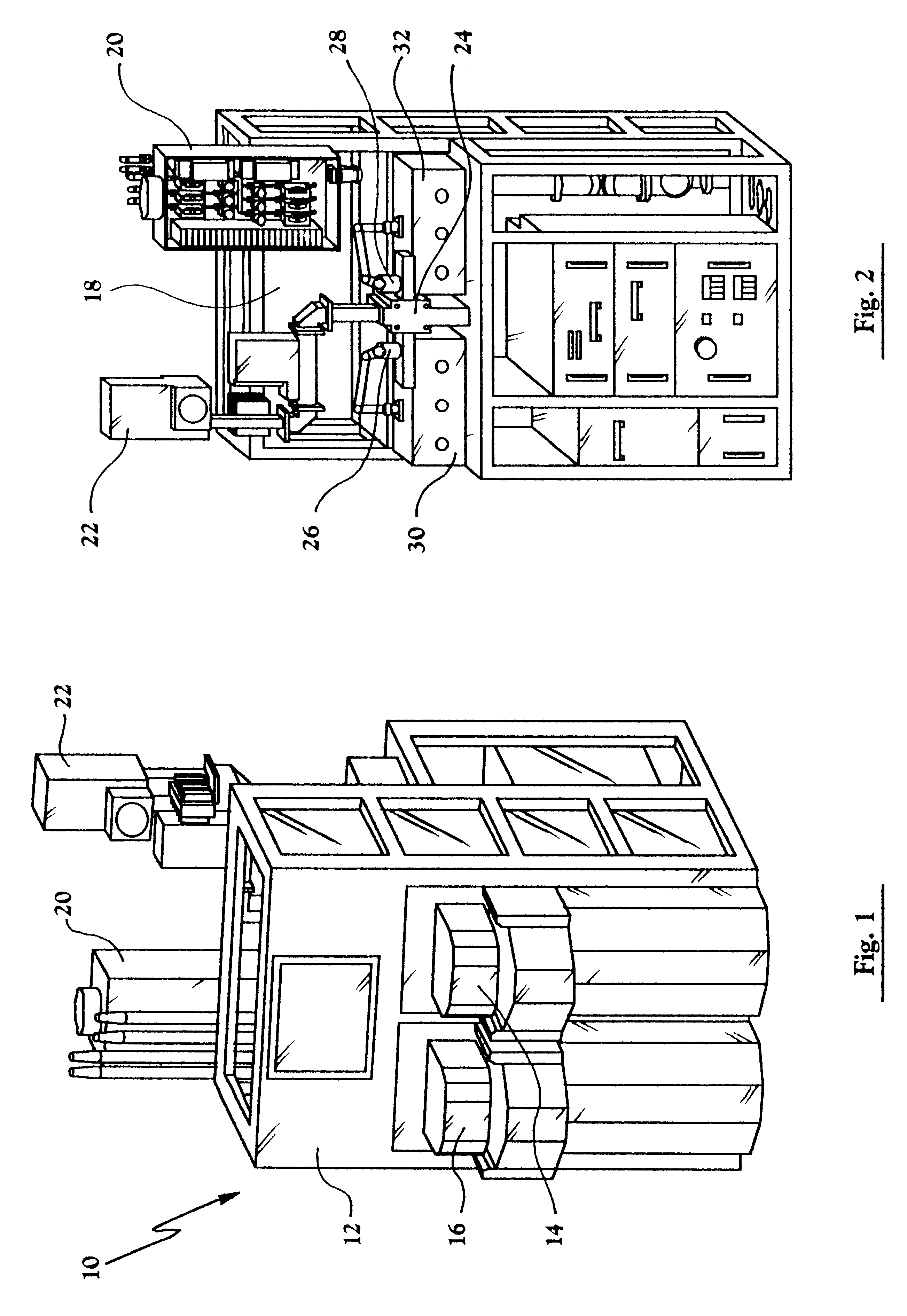
1. The overall system architecture eliminates redundant parts and, through sharing of components allows, the overwhelming majority of high cost subsystems to be amortized between the two process chambers, including, for examnple, the common switchable RF power supply, throttle valve, gas box, pressure transducers, and vacuum pumps.
2. This invention is applicable to both deposition and etch semiconductor processes and their variations, including, for example, photoresist removal, wafer cleaning, and t

Problems solved by technology

Although plasmas can be created at atmospheric pressure, they are very difficult to ignite, difficult to control, consume enormous power, generate intense UV light, and are awkward to confine.
This vacuum processing contributes substantially to the high cost of semiconductor processing equipment itself (vacuum pumps alone cost about $40,000.00) and the relatively excessive amount of time (typically 65-80% of a complete cycle) spent in the overhead tasks of pumping a vacuum, venting to atmosphere, transferring wafers to and from, opening and closing doors, metering gases in and out, and the like.
Moreover, each of these subsystems is typically contained in a multi-chamber machine, providing 100% redundancy at great expense in terms of equipment cost and space.
On one hand, when examining the cost of semiconductor wafer processing equipment, one quickly realizes that relatively few system components comprise the vast majority of the total equipment costs.
While achieving some economies through a common vacuum and by an autom

Method used


Image

  • Synchronous multiplexed near zero overhead architecture for vacuum processes
  • Synchronous multiplexed near zero overhead architecture for vacuum processes
  • Synchronous multiplexed near zero overhead architecture for vacuum processes

Examples


working example 2

11. Working Example 2

As seen schematically in FIGS. 19-20 the robot movements are those of a modified form of the working example of FIG. 17 but still similar in many respects. In FIGS. 19-20 the robot may be viewed as always standing facing toward chamber 2 and cassette 2 as seen in FIG. 19 step #1 with his left arm adjacent chamber 1 and the right arm adjacent cassette 1 and not turning 180 degrees to move a wafer from a cassette to a chamber, and, vice versa. In all other respects working examples 1 and 2 are identical.

Thus, as seen sequentially in FIGS. 19,20, wafer 1 is removed from cassette 1 (#1) and placed in chamber 1 for processing (#2); wafer 2 is removed from cassette 1 (#3) and placed in chamber 2 for processing (#4); wafer 3 is removed from cassette 1 (#5) and, as chamber 1 finishes processing, wafer 1 is removed from chamber 1 (#6) and replaced by wafer 3 (#7), and wafer 1 is stored in its original slot in cassette 1 (#8); wafer 4 is removed from cassette 1 (#9) and, ...

working example 3

12. Working Example 3

As seen in FIG. 30 the movements are those of a robot of a third working example of an embodiment of the present invention in which dual downstream or in-chamber reactors are each running the same single process using a single exterior (relative to the vacuum) 25-wafer cassette and a single exterior robot with two front arms (as was the robot of working example 2 in FIGS. 19-20), eight separate portions of which are shown enlarged in FIGS. 22-29 for ease in reading the function steps. In this working example, all of the odd numbered wafers are processed in chamber 1 and all of the even numbered wafers are processed in chamber 2, but all wafers are returned to their original slots in the single cassette. Otherwise, the process steps are the same as in the prior working examples. Microwave energy is used in this example. Additionally, while the sequence is shown for a single cassette, actually the sequence can repeat relative to a cassette #2, #3, and #4, or even ...


PUM

PropertyMeasurementUnit
Timeaaaaaaaaaa
Pressureaaaaaaaaaa
Poweraaaaaaaaaa

Abstract

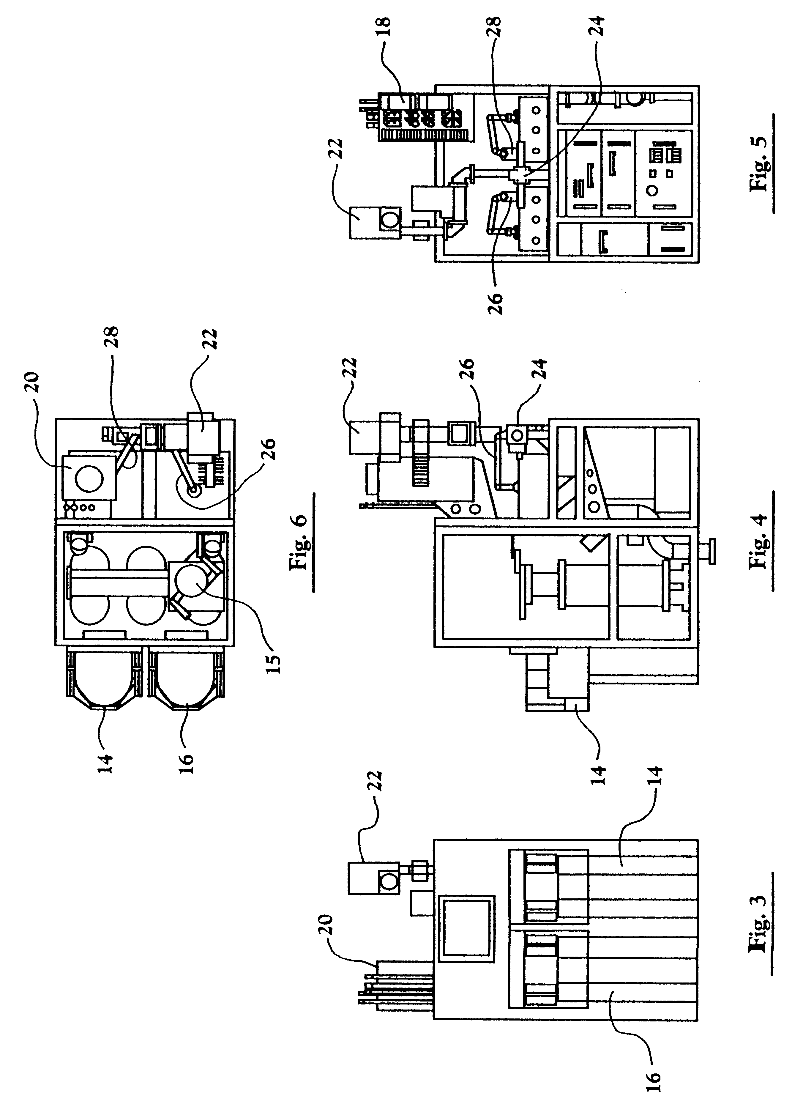
Workpieces, such as, semiconductor wafers, are continuously manufactured by repetitively alternately switching a common radio frequency power source between a plurality of downstream or in-chamber processing reactors and actively processing one workpiece in a vacuum in an operating one of the processing chambers while simultaneously executing with a robot at atmospheric pressure the overhead tasks relative to next processing another workpiece in the other processing chamber. The active processing of the workpieces in alternate chambers does not overlap, and the robot starts and completes all of its preparatory tasks during the active processing step during the time when a chamber's door is closed thereby providing virtual zero overhead. System architecture allows eliminating all redundant components other than the dual chambers which operate in parallel. For a modest cost increase for the second chamber throughput is trebled and overall costs significantly reduced. Preferred modes include switching a common microwave power source between the pair of processing chambers, pumping down with a common vacuum pump, and stabilizing the chamber pressure with a common throttle valve.

Description

1. Fields of the InventionThe present invention relates generally to an apparatus and method for reducing workpiece handling overhead relative to active workpiece processing time in a manufacturing process, and, more particularly, to reducing the relative time spent pumping a vacuum in semiconductor wafer processing chambers, venting such chambers to atmosphere, and transferring wafers to and from such chambers while increasing the relative time spent actively processing the wafers in the chambers, such as, by actively etching, stripping, and depositing the semiconductive layers of the wafers, and, even more particularly, to the process of switching common RF or microwave power supply sources alternately between dual downstream or in-chamber plasma reactors and alternately actively processing in one reactor while performing the aforesaid overhead tasks on the other reactor thereby significantly increasing the throughput of the overall machine at overall reduction in equipment cost c...

Claims


Application Information

Patent Timeline
IPC IPC(8): H01L21/00H01L21/302H01L21/02H01L21/3065H01L21/677
CPCH01L21/67017H01L21/6719H01L21/67196H01L21/67253H01L21/67745H01L21/30
Inventor COX, GERALD M.
Owner LAM RES CORP
Why Eureka
Try Eureka