Method and apparatus for performing optical coherence-domain reflectometry and imaging through a scattering medium

a scattering medium and optical coherence domain technology, applied in the field ofconfocal microscopy and optical coherence domain reflectometry (ocdr), can solve the problems of inability to perform high resolution measurements through light scattering materials, reduced signal to noise ratio of devices, and needing a more powerful light source, etc., to achieve high spatial resolution

Inactive Publication Date: 2001-05-15
OPTICAL BIOPSY TECH
View PDF3 Cites 54 Cited by
  • Summary
  • Abstract
  • Description
  • Claims
  • Application Information

AI Technical Summary

Benefits of technology

Accordingly, it is a primary object of the present invention to provide a method and apparatus for reflectance measurements through light scattering materials that:1) requires fewer active components than prior art techniques;2) utilizes all the light reflected from the sample;3) provides an improved signal to noise ratio compared to prior art techniques;4) is able to scan deep into scattering materials such as biological tissue;5) is able to produce vertical-section, horizontal-section, or three dimensional images;6) has short data acquisition times for real-time in-vivo imaging of live tissue;7) has high spatial resolution thus enabling the imaging of microscopic structures such as biological structures; and8) is easy and inexpensive to manufacture.These and other objects and advantages will be apparent upon consideration of the following description and accompanying drawings.

Problems solved by technology

Optical time domain reflectometry (OTDR) and optical frequency domain reflectometry (OFDR) are techniques which are used to examine optical systems and are generally not capable of performing high resolution measurements through a light scattering material.
This is undesired because it decreases the signal to noise ratio of the device and results in a more powerful light source being required.
The use of a moving mechanical mirror is a disadvantage because moving mechanical parts often have alignment and reliability problems.
Another disadvantage of the device of FIG. 1 is the requirement for a large depth of focus of the probe beam in sample 24.
This requirement increases the minimum spot size of the beam, and thus limits the spatial resolution of the device when acquiring images.
A further disadvantage of the device of FIG. 1 is the long integration time typically necessary for each measurement point (pixel) when acquiring an image.
Under these conditions, the slow acquisition time does not allow in-vivo imaging of live tissue which is usually in motion.
However, Sorin's device requires a coupler in the light path between the source and sample and so necessarily wastes 50% of the light reflected from the sample.
In other words, only 50% of the light reflected by the sample is amplified and contributes to the interference signal.
Consequently, Sorin's device produces less than optimum signal to noise ratio resulting in less accurate measurements.

Method used


Image

  • Method and apparatus for performing optical coherence-domain reflectometry and imaging through a scattering medium
  • Method and apparatus for performing optical coherence-domain reflectometry and imaging through a scattering medium
  • Method and apparatus for performing optical coherence-domain reflectometry and imaging through a scattering medium

Examples


Embodiment Construction

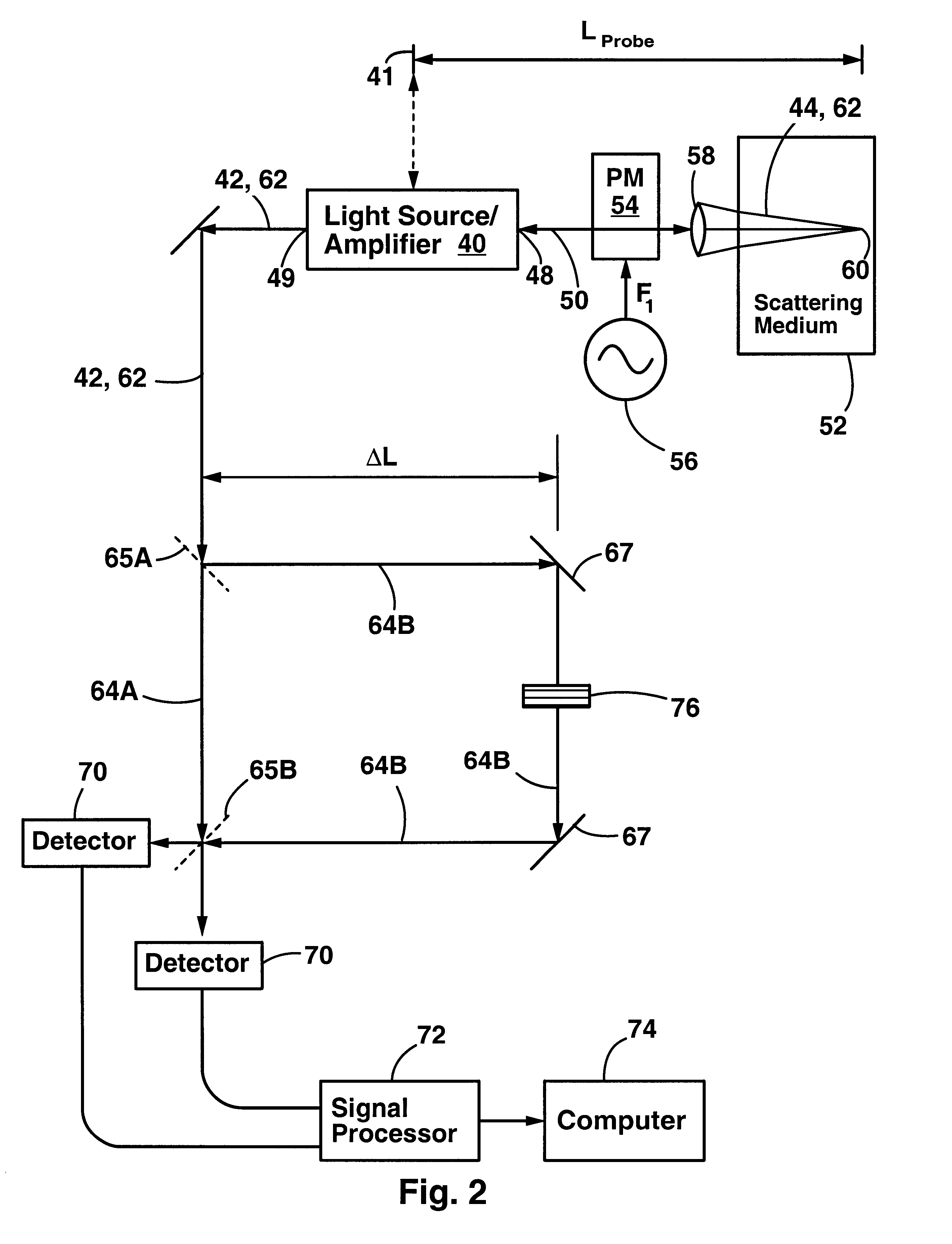
FIG. 2 shows a first embodiment of an apparatus for performing optical coherence domain reflectometry on a sample of light scattering media. In the first embodiment, the apparatus is constructed from bulk optical components. A two output light source 40 illuminates a sample 52 with a probe beam 44. The sample comprises a light scattering medium such as biological tissue. The light source emits the probe beam 44 from a probe aperture 48. The light source also emits a reference beam 42 from a reference aperture 49. The reference beam 42 is emitted directly into an interferometer having a short arm 64A and a long arm 64B. The interferometer shown is a Mach-Zehnder type, but other types can be used as well. The interferometer outputs light into two optical detectors 70 which detect interference. The detectors output to a signal processor 72 and a computer 74.

The light source 40 preferably has a relatively short coherence length in the range of 30 to 3000 microns. The reference beam 42 a...


PUM


Abstract

An apparatus and method for performing optical coherence domain reflectometry. The apparatus preferably includes a single output light source to illuminate a sample with a probe beam and to provide a reference beam. The reference beam is routed into a long arm of an interferometer by a polarizing beamsplitter. A reflected beam is collected from the sample. A 90.degree. double pass polarization rotation element located between the light source and the sample renders the polarizations of the probe beam and reflected beam orthogonal. The polarizing beamsplitter routes the reflected beam into a short arm of the interferometer. The interferometer combines the reference beam and the reflected beam such that coherent interference occurs between the beams. The apparatus ensures that all of the reflected beam contributes to the interference, resulting in a high signal to noise ratio.

Description

FIELD OF THE INVENTIONThis invention relates generally to confocal microscopy and optical coherence domain reflectometry (OCDR). More specifically, it relates to devices for measuring optical reflectance and imaging through a thickness of biological tissue.BACKGROUND OF THE INVENTIONThere are a number of applications for techniques for optical measurement through light scattering materials. Most notably, such measurements can be performed through biological tissues and therefore can be used for noninvasive medical diagnostic tests. Cancer tissue and healthy tissue, for example, can be distinguished by means of different optical properties. Scanning the optical measurement can yield high contrast and high magnification images of biological tissues. For example, imaging techniques could be used to examine plaque on the interior walls of arteries and vessels or other small biological structures. Related applications extend to the examination and troubleshooting of integrated optical ci...

Claims


Application Information

Patent Timeline
Patent Type & Authority Patents(United States)
IPC IPC(8): A61B5/00
CPCA61B3/102
Inventor MANDELLA, MICHAEL J.GARRETT, MARK H.KINO, GORDON S.
Owner OPTICAL BIOPSY TECH
Why Eureka
Try Eureka