Inter-switching heat accumulating regenerative burner system

a regenerative burner and heat accumulating technology, which is applied in the direction of furnaces, combustion types, and combustion using lumps and pulverulent fuels, etc., can solve the problems of insufficient formation, limited non-stationary flame formation, and inability to maintain high air velocity in operation

a regenerative burner and heat accumulating technology, which is applied in the direction of furnaces, combustion types, and combustion using lumps and pulverulent fuels, etc., can solve the problems of insufficient formation, limited non-stationary flame formation, and inability to maintain high air velocity in operation

US6234789B1Inactive Publication Date: 2001-05-22NIPPON FURNACE KOGYO KAISHA LTD

Image

  • Inter-switching heat accumulating regenerative burner system
  • Inter-switching heat accumulating regenerative burner system
  • Inter-switching heat accumulating regenerative burner system

Examples


Embodiment Construction

The structure of the present invention will now be described in detail in connection with the illustrative best modes thereof.

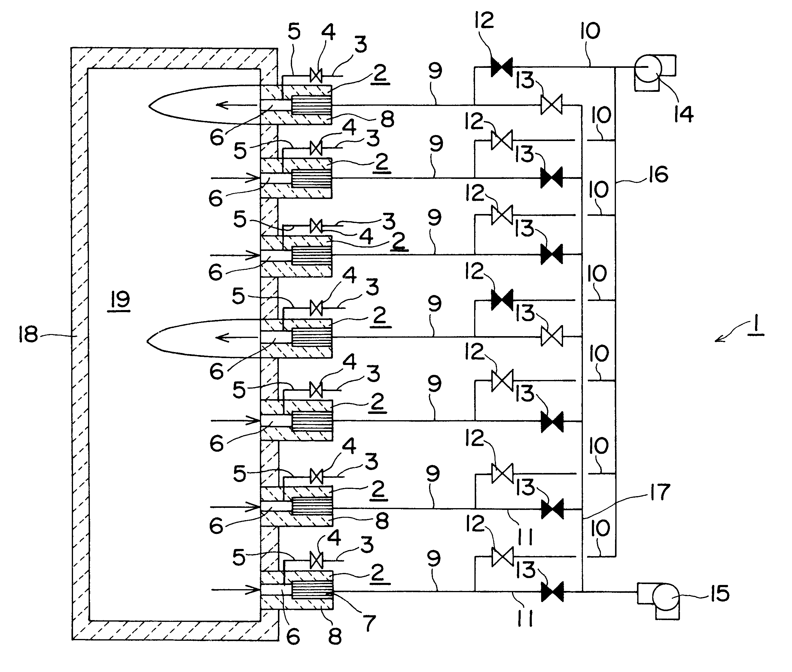
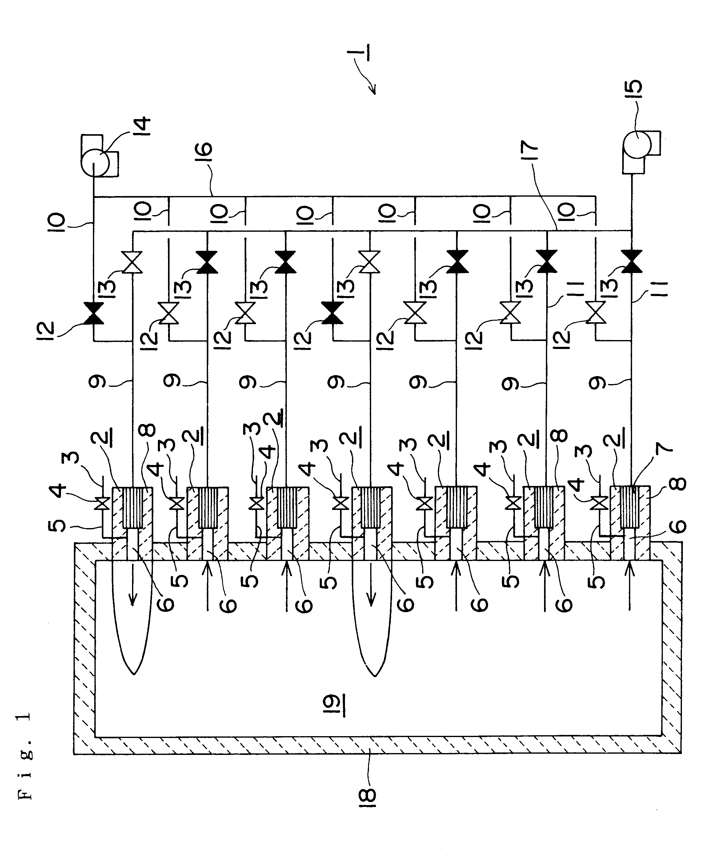
FIG. 1 shows a preferred embodiment of an alternate changeover regenerative burner system (which will be simply referred to as a burner system hereinafter) according to the present invention. With an alternate changeover regenerative burner consisting of a burner 2 having a regenerator 7 and air supply / exhaust switching devices 12 and 13 for switching connection to an air supply system and an exhaust system of the burner 2 being regarded as a module unit, the burner system 1 is constituted by three or more units, i.e., seven units. It is to be noted that reference numerals 9, 10 and 11 denote ducts and 18 designates a furnace enclosure.

This burner system 1 is composed of seven units of the alternate changeover regenerative burners 2 for realizing the so-called high-temperature combustion and a control system for appropriately selecting these units to perform ...


PUM


Abstract

The present invention provides an alternate changeover regenerative burner system suitable for use as a heat source for an industrial furnace and the like where re-increase in temperature is relatively-often carried out; an alternate changeover regenerative burner constituted by a burner 2 having a regenerator 7 and air supply / exhaust switching mechanisms 12 and 13 for switching connection with an air supply system 17 and an exhaust system 16 of the burner 2 is regarded as a module unit; and three or more units of the alternate changeover regenerative burner constitute a combustion system 1; a ratio of the number of the burners 2 performing combustion and the number of the burners 2 being stopped is variable; and combustion is controlled in such a manner that all the units sequentially repeat alternate regenerative combustion with the units forming no fixed pairs. According to the present invention, a flow velocity of air injected from a burner throat can be variable irrespective of a quantity of combustion; the flow velocity of air emitted from the burner throat can be maintained high even if the operation is carried out with a quantity of combustion lower than the burner capacity; and a non-stationary flame can be formed in a wider range.

Description

The present invention relates to an alternate changeover regenerative burner system. More particularly, the present invention relates to an alternate changeover regenerative burner system suitable as a heat source for an industrial furnace and others in which re-increase in temperature is relatively often performed.DESCRIPTION OF THE PRIOR ARTA prior art alternate changeover regenerative burner system comprises: a pair of burners each of which has a regenerator; and air supply / exhaust switching means for switching supply and exhaust of oxidizer such as air, oxygen-enriched air, pure oxygen and others (which will be simply referred to as combustion air in this specification) between this pair of burners, and the system alternately burns the pair of burners (the currently-burning burner will be referred to as a burner performing combustion) and exhausts gas in a furnace from a non-combusting burner (which will be referred to as a burner performing exhaust) to recollect heat of the exh...

Claims


Application Information

Patent Timeline
22 May 2001
Publication
US6234789B1
IPC
F23L15/00; F23C5/08; F23C5/00; F23L15/02; F23N5/00
CPC
F23C5/08; F23L15/02; Y02E20/34
Inventors
MIYATA, MAKOTO