Producing method of a film-type transmission line and method of connecting to an existing line

a transmission line and film-type technology, applied in the direction of waveguides, soldering devices, high-frequency circuit adaptations, etc., can solve the problems of significant transmission loss, relatively high signal reflection, and disadvantage of developing an impedance irregularity on an overlapped area

Inactive Publication Date: 2001-06-05
TOYOTA JIDOSHA KK
View PDF11 Cites 50 Cited by
  • Summary
  • Abstract
  • Description
  • Claims
  • Application Information

AI Technical Summary

Problems solved by technology

The connection through a ribbon in the prior art has disadvantages that a characteristic-impedance irregularity occurs at each junction, reflection of a signal is relatively high, and transmission loss is significant.
In addition, the film substrate 101 and the substrate of high permittivity 102 are required to overlap

Method used


Image

  • Producing method of a film-type transmission line and method of connecting to an existing line
  • Producing method of a film-type transmission line and method of connecting to an existing line
  • Producing method of a film-type transmission line and method of connecting to an existing line

Examples


Embodiment Construction

The following describes a preferred embodiment of the present invention with reference to the drawings.

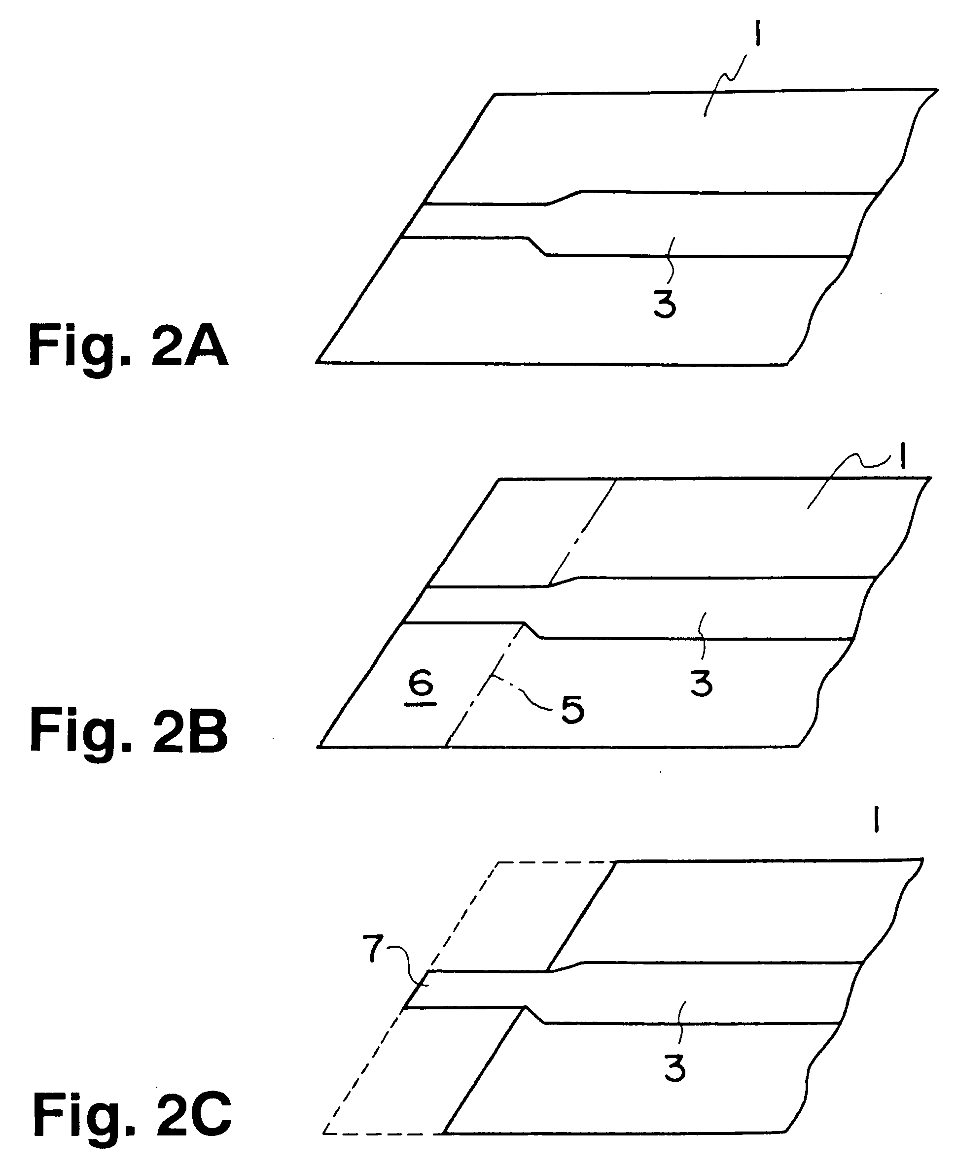
A method for producing a film-type transmission line is described with reference to FIG. 2. First, a transmission line pattern 3 is formed on a single side of a film substrate 1 through a conventional method known well (FIG. 2a). The film-type transmission line is, for example, a strip (triplate) line or a suspended line. Material of the film substrate 1 is such as polyimide or polyester and material of the transmission pattern 3 is copper.

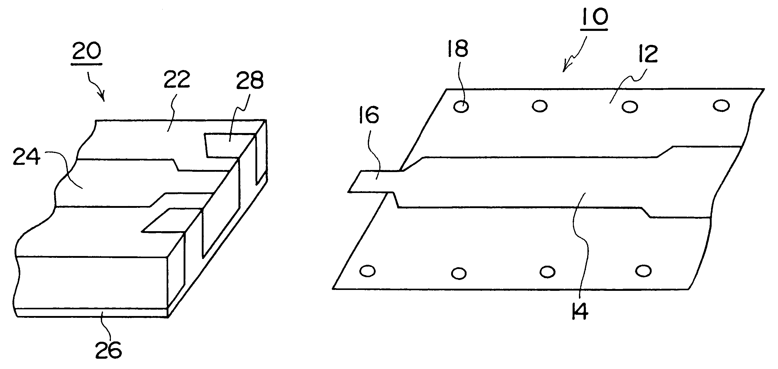
Next, the film substrate 1 is etched along an etching line 5 of FIG. 2b using a laser, such as an impact laser or excimer laser. A border area 6 of the film substrate 1 is removed to leave the transmission line pattern 3. As a consequence of this, an exposed connecting portion 7 is formed as shown in FIG. 2c. The exposed connecting portion 7 is an extended part of the line pattern 3 and protrudes from the film substrate 1. Therefore the face on a...


PUM

PropertyMeasurementUnit
Dielectric polarization enthalpyaaaaaaaaaa
Areaaaaaaaaaaa
Frequencyaaaaaaaaaa

Abstract

An exposed connecting portion is formed by partially removing a film substrate by such laser etching while leaving a transmission line pattern. A film-type transmission line is placed in such a manner as to overlap the exposed connecting portion and a transmission line pattern on a side to be connected. Bonding, for example thermo compression bonding, is applied to the two overlapped line patterns. Since a gold ribbon is not used and overlapping of a high-dielectric substrate and the film substrate is unnecessary, impedance irregularity is reduced. This makes it possible to carry out bonding without the medium of the film substrate and a connection with high reliability may be achieved.

Description

1. Field of the inventionThe present invention generally relates to a method for producing a film-type transmission line and a method for connecting the line, and more particularly to a reduction of impedance irregularity at a junction of a transmission line.2. Description of the Related ArtFIG. 1 shows a conventional constitution of a junction between a film substrate and a high-dielectric substrate in a high-frequency circuit of such a radar system. Prior art generally attempts to perform ribbon bonding using a gold ribbon. A film substrate 101 and a substrate of high permittivity 102 (e.g. ceramic) are constituted of transmission line patterns 103 and 104 respectively. The film substrate 101 is placed over the substrate of high permittivity 102 and a gold ribbon 105 lying astride both of the substrates is crimped through thermocompression bonding.A method of connection of this type is shown in Japanese Patent Laid-Open Publication No. Hei 7- 170115. In FIG. 1 of the patent docume...

Claims


Application Information

Patent Timeline
IPC IPC(8): H01P5/08H01P1/04H05K1/02H05K3/36H01P3/02H01P3/08H01P5/02H01P11/00
CPCH01P1/047H01P5/08H01L2224/1134H01L2224/13144H05K1/0237H05K3/361H01L2924/00014H01L2924/00013H01L2224/13099
Inventor KURODA, KAZUSHI
Owner TOYOTA JIDOSHA KK
Why Eureka
Try Eureka