Magnetic disk drive with a floating head slider having projections arranged to float at a greater distance from magnetic disk than slider trailing end

a technology of magnetic disk and projection, which is applied in the direction of maintaining head carrier alignment, manufacturing head surface, instruments, etc., can solve the problems of difficult to form a large number of head sliders in the crown shape, the suspension of the head slider is easily damaged and broken, and the magnetic disk cannot be rotated

Inactive Publication Date: 2001-06-12
TOSHIBA STORAGE DEVICE CORP
View PDF37 Cites 35 Cited by
  • Summary
  • Abstract
  • Description
  • Claims
  • Application Information

AI Technical Summary

Benefits of technology

Also, the second object of the present invention is to provide a head slider which is stably operated when a flying operation is started or stopped and is manufactured at a high yield rate. Also, the second object is to provide a magnetic recording drive utilizing the head slider and a manufacturing method of the head slider.
In cases where the second mask is formed out of the dry film resist, air bubbles can be easily confined in a clearance between the first mask and the second mask. However, the thickness of the first mask is set to 10 .mu.m or less, any air bubble is not confined between the first mask and the second mask. Therefore, the second mask can be accurately patterned to form the concave portion, and the shape of the rail plane can be set with a high accuracy.

Problems solved by technology

In this case, because a torque of a spindle motor for rotating the magnetic disk is decreased as the magnetic disk apparatus are downsized, there is a case that the magnetic disk cannot be rotated because of the weakness of the torque.
Also, the suspension for supporting the head slider, is easily damaged and broken when the rotation of the magnetic disk is started.
However, though the head slider formed in a crown shape is effective to prevent the stiction, it is difficult to form a large number of head sliders in the crown shape with the tight accuracy for mass production.
Therefore, there is a drawback that a spacing loss occurs.
Therefore, it is difficult to precisely adjust a height of the projection by controlling an etching time required to etch the rail surface, and there is a drawback that a yield rate of the projection is lowered.
This causes large friction of the projection surfaces on the disk surface.
As a result, the projections wear out rapidly.
Also, even though a plurality of projections are provided on the head slider, when the number of projections is decreased to reduce the contact area, a contact pressure at the contact area of the projections is increased, and there is a case that the lubricant layer of the magnetic disk is worn away.
As a result, a solid-to-solid contact area is increased, and the surfaces of the projections and the magnetic disk are worn because of friction between the projections and the magnetic disk.
Because each of the projection elements is made of a hard material such as amorphous carbon, diamond-like carbon or oxide, it is difficult to cause damage to the projection elements.
If all projections were made low in height, the rail plane other than the projections might come into contact with the magnetic disk due to a distortion produced on the head slider.
However, because an area of the top portions of the second projections is larger than that of the first projections to increase a mechanical strength of the second projections, the slider has a superior durability, and it is difficult to do damage to the slider.
Because the lubricant covering the top portion of each of the projections is made of a fluorine-contained lubricant having water repellency, it is difficult that water is concentrated around each of the projections.
Also, because the fluorinate carbon has water repellency, it is difficult that water is concentrated around each of the projections.

Method used


Image

  • Magnetic disk drive with a floating head slider having projections arranged to float at a greater distance from magnetic disk than slider trailing end
  • Magnetic disk drive with a floating head slider having projections arranged to float at a greater distance from magnetic disk than slider trailing end
  • Magnetic disk drive with a floating head slider having projections arranged to float at a greater distance from magnetic disk than slider trailing end

Examples


first embodiment

(The First Embodiment)

Preferred embodiments according to the first concept of the present invention are first described with reference to drawings to solve the first object.

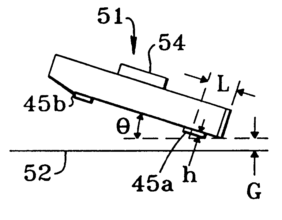
FIG. 1(a) is a schematic plan view of a magnetic head slider according to the first embodiment of the present invention. FIG. 1(b) is a schematic side view of the magnetic head slider shown in FIG. 1(a).

As shown in FIG. 1(a), a pair of rail planes 4 respectively having a flat rail surface are placed on both sides of a magnetic head slider 2 to form a concave portion between the rail planes 4. A magnetic transducer (or a head device) 6 is attached on an air outflow end (or the trailing edge of the head slider 2) of one rail plane 4 from which an air flow is output, and a pair of projections 8 formed of rectangular-shaped thin films are arranged on the rail planes 4 near an air inflow end (or the loading edge of the head slider 2) from which the air flow is input. Each of the projections 8 is made of a hard materia...

second embodiment

(The Second Embodiment)

FIG. 4(a) is a schematic plan view of a magnetic head slider according to the second embodiment of the present invention. FIG. 4(b) is a schematic side view of the magnetic head slider shown in FIG. 4(a).

Elements in the second embodiment and following embodiments which are the same as those in the first embodiment are denoted by the same reference numerals as those in the first embodiment, and the description of the same elements is omitted to avoid a duplicate description.

As shown in FIGS. 4(a) and 4(b), corners of the rail planes 4 placed on the air inflow end side of the rail planes 4 are cut off in a taper shape to form taper surfaces 7 on the air inflow end side of the rail planes 4. In the above configuration, an airflow input from the air inflow end side is not disturbed by any corner of the rail planes 4 but smoothly passes along the taper surfaces 7 to give a floating force to the head slider 2. Therefore, any adverse influence exerted on the flying o...

third embodiment

(The Third Embodiment)

FIG. 5(a) is a schematic plan view of a magnetic head slider according to the third embodiment of the present invention. FIG. 5(b) is a schematic side view of the magnetic head slider shown in FIG. 5(a).

As shown in FIGS. 5(a) and 5(b), the taper surfaces 7 are formed on the air inflow end side, and a pair of projections 8a are arranged on boundary areas ranging from the taper surfaces 7 to the rail planes 4, in place of the projections 8. Because parts of the projections 8a are arranged along the taper surfaces 7, an airflow input from the air inflow end side is not disturbed by side surfaces of the projections 8a but smoothly passes along surfaces of the projections 8a facing the magnetic disk 10. Therefore, any adverse influence exerted on the flying of the head slider 2 can be avoided, and the head slider 2 can more stably fly over the surface of the magnetic disk 10 during the rotation of the magnetic disk 10.

Because the projections 8a are formed to have a ...


PUM

PropertyMeasurementUnit
heightaaaaaaaaaa
heightaaaaaaaaaa
flying heightaaaaaaaaaa

Abstract

A head slider is composed of a substrate having a transducer on its outflow end, a rail plane formed on a surface near both sides of the substrate facing a magnetic disk. The head slider further includes a plurality of projection elements formed on the rail plane. When the slider is floating over the magnetic disk, the distance between the projection elements and the magnetic disk is greater than the distance between the outflow end of the slider and the magnetic disk.

Description

1. Field of the InventionThe present invention relates generally to a magnetic recording drive, a head slider of the magnetic recording drive, a manufacturing method of the head slider, and more particularly to a head slider operated according to a contact start stop (CSS) method, a magnetic recording drive in which the head slider can float over a surface of a magnetic recording medium, and a manufacturing method of the head slider.2. Description of the Prior ArtIn a magnetic disk apparatus, a flying head operated according to a contact start stop (CSS) method is adopted. In the CSS method, a magnetic head makes contact with a surface of a magnetic disk when the magnetic disk apparatus is not in operation. A head slider of the magnetic head is lifted up from the magnetic disk surface when the magnetic disk drive is in operation. Therefore, the head slider of the magnetic head slides over the magnetic disk surface when the disk stands and stops. In this case, a read-write magnetic h...

Claims


Application Information

Patent Timeline
Patent Type & Authority Patents(United States)
IPC IPC(8): G11B5/84G11B5/72G11B5/60G11B5/725G11B5/31G11B5/255G11B23/50G11B5/40
CPCG11B5/6005G11B5/72G11B5/725G11B5/8408G11B5/255G11B5/3106G11B5/3163G11B5/40G11B23/507G11B5/6082G11B5/7266
Inventor KASAMATSU, YOSHIHARUYOKOHATA, TORUYAMAMOTO, TAKAYUKITOYOGUCHI, TAKASHIYONEOKA, SEIJIMIZOSHITA, YOSHIFUMI
Owner TOSHIBA STORAGE DEVICE CORP
Why Eureka
Try Eureka