Method and apparatus for washing and drying semi-conductor devices

a technology of semi-conductor devices and washing machines, applied in lighting and heating apparatus, liquid processing with progressive mechanical movement, combustion process, etc., can solve the problems of ineffective cleaning of such closely packed devices, limited cleaning parameters which are much needed, and inability to achieve close pitching when attached in a straight line. , to achieve the effect of low operating cost and high and consistent cleaning efficiency

Inactive Publication Date: 2001-06-26
ULTRA CLEAN TECH ASIA
View PDF17 Cites 31 Cited by
  • Summary
  • Abstract
  • Description
  • Claims
  • Application Information

AI Technical Summary

Benefits of technology

It is another object to provide a cleaning apparatus which gives high and consistent cleaning e

Problems solved by technology

When these nozzles are attached a cross the spray manifold or hose, they cannot achieve close pitching when attached in a straight line.
With the bulky size of the spray nozzles, cleaning of such closely packed devices become ineffective.
These types of design limits the cleaning parameters which are much needed to enhance cleaning actions.
When angled spray jets with a 0.degree. direction of spray are used to clean parts having very light weight, such as a plastic ball grid array (BGA) strip, the mesh-type conveyor belt which is suppose to transport the strip across the various zones may not function effectively.
The sandwich effect of a strong top and bottom spray at high velocity and pressure may pin the device at a stationary position due to slippage relative to the belt.
This problem is compounded by the fact that most semi-conductor packages are cleaned in the"dead-bug" position, with the plastic packaging in contact with the conveyor mesh.
When the package slips and travels inconsistently, the travel time and spray contact time (i.e. cleaning time) becomes inaccurate.
This results in loss of yield and cleaning efficiency of the conventional equipment.
Physical principles dictate that a severe pressure drop would result across these conduit, resulting in a significant drop in velocity of the sprays which are directly proportional to the distance from the fluid source.
The notches, however, are limiting when the type of devices to be cleaned is changed during batch production because of the amount of time needed to c

Method used


Image

  • Method and apparatus for washing and drying semi-conductor devices
  • Method and apparatus for washing and drying semi-conductor devices
  • Method and apparatus for washing and drying semi-conductor devices

Examples


Embodiment Construction

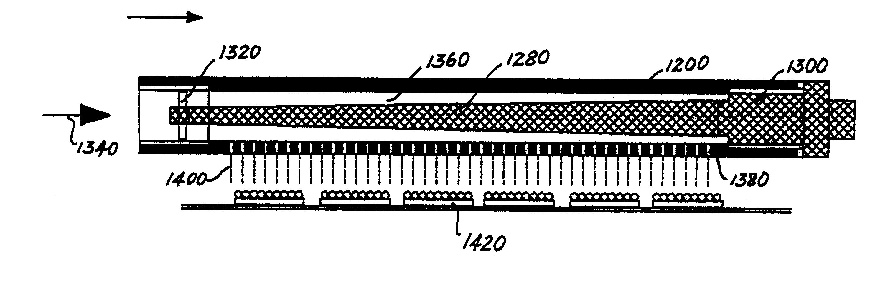
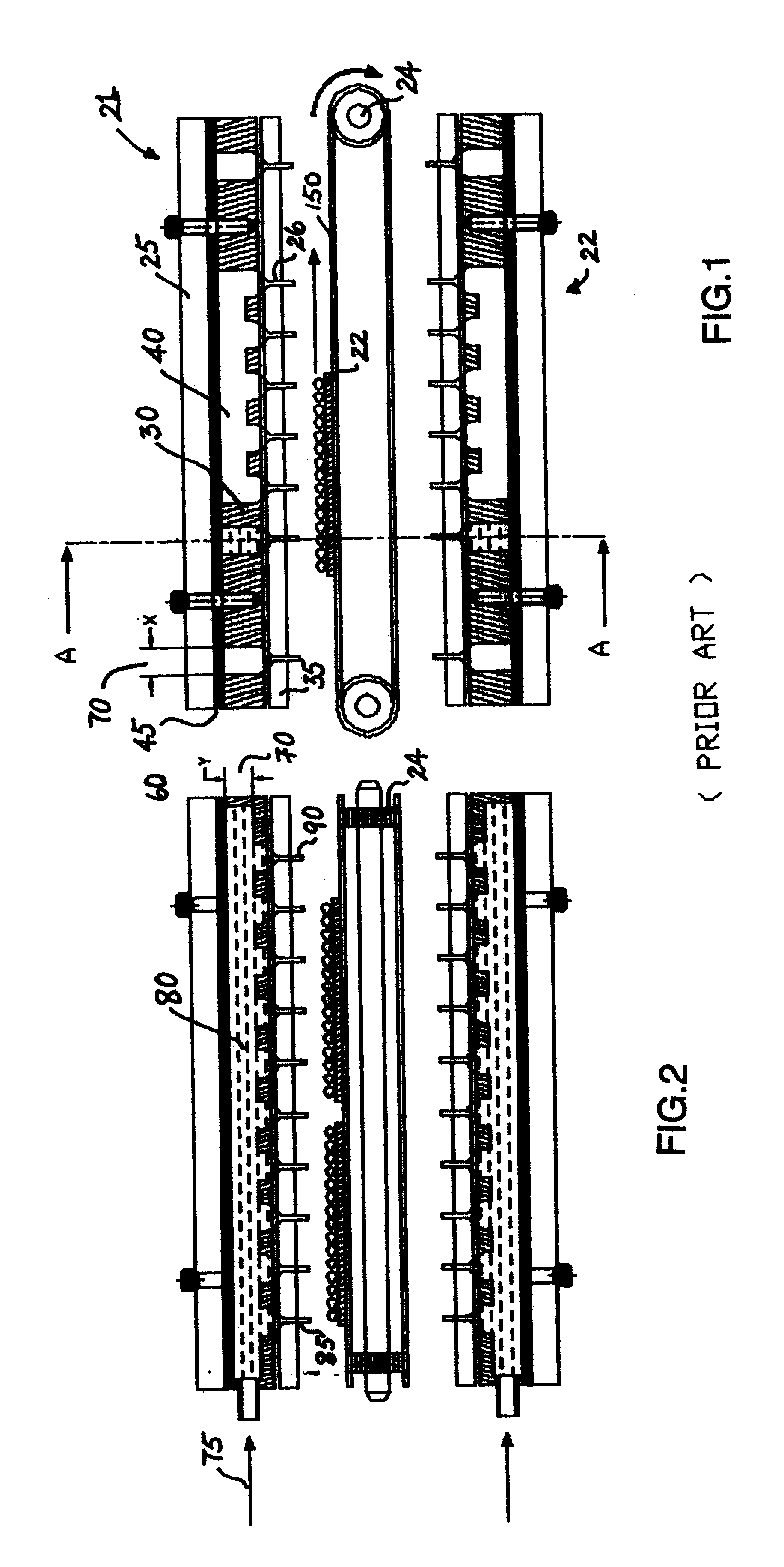
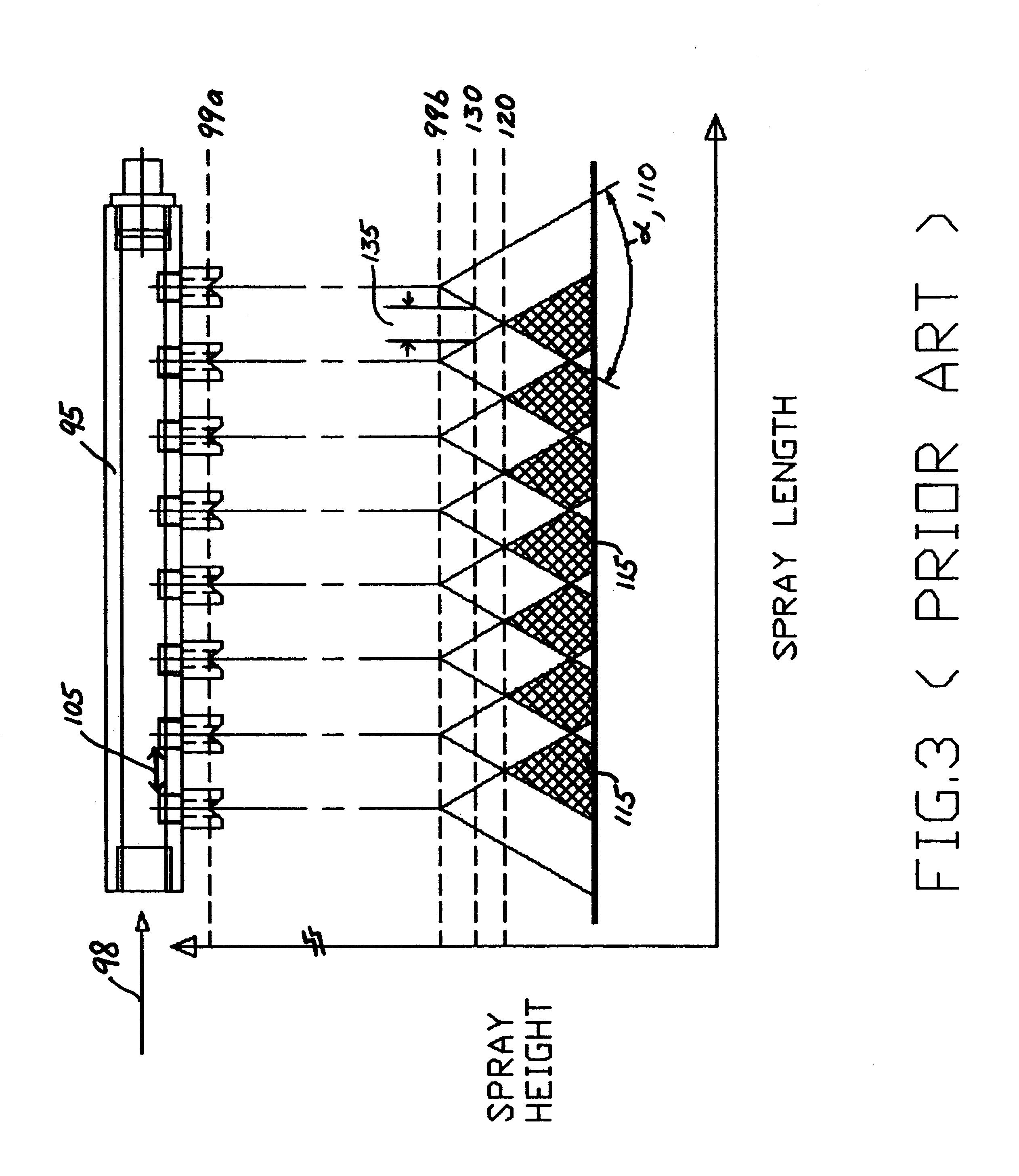
An apparatus for achieving state-of-the art cleaning is described. The preferred embodiment comprises a conveyor disposed within a housing or chassis, and a set of spray tools. A pump system delivers pressurized fluid from tanks to strainer, valves, filters and / or ion exchange resins to finally exit through spray tunnels or wands onto the devices to be cleaned. The spray tools can be grouped into one or more sections, such as a wash, rinse, and drying sections.

The prewash or wetting spray wand in the wash section preferably function with chemicals or water as the wash fluid or medium, followed by a series of wash sprays, and ends with an isolation process, which prevents the wash medium from crossing over to the next rinsing stage. The pre-rinse spray wand removes the chemical on the devices from the wash section, followed by a series of spray wands which washes completely the remaining in residue from the device. Another isolation spray wand which uses for example nitrogen gas, is ...


PUM

PropertyMeasurementUnit
Diameteraaaaaaaaaa
Diameteraaaaaaaaaa
Distanceaaaaaaaaaa

Abstract

A cleaning apparatus which comprises a spray cleaning arrangement capable of even cleaning of devices. The cleaning arrangement is disposed within a housing, and is directed towards a conveyor belt, which transports the device to be cleaned across the various wash, rinse and drying zones of the apparatus. At least one spray wand is provided for the circulation of a wash fluid having at least one row of holes disposed longitudinally thereacross for releasing the wash fluid onto the device to be washed. The spray wand has a decreasing internal traverse cross-sectional area from one end to the second end such that a substantially uniform internal pressure is maintained between the two ends during washing. The holes on the spray wands are preferably microtunnels which can be disposed at high density along the spray wand. The spray wand can also be rotated such that the direction of spray may be adjusted. The various wash, rinse and drying zones are ideally designed as modules with their own conveyor belts, such that contamination due to fluid carry-over is minimized. A top guiding system is also provided directional control to the moving devices.

Description

The present invention is related to washing apparatus and method of using the same. In particular, the present invention is related to a method and apparatus for cleaning and drying of semi-conductor devices.The art of cleaning generally consists of multiple zones of treatment; namely, a wash zone, a rinse zone and a dry zone. The wash zone typically contain a prewash section, a wash section and an air isolation section. In addition, there is a rinse section which typically includes a first rinse section to wash away the chemical from the wash section, a rinse section, a final rinse section and an isolation section. The final drying section generally contains an air isolation section, and the heated air dry section. A central exhaust system located at the top of the entire apparatus acts to extract fumes generated from the washing actions, which are extracted by the central exhaust blower external to the cleaning apparatus. There is also a conveyor transport system which runs across...

Claims


Application Information

Patent Timeline
IPC IPC(8): B08B3/02B05B1/14B05B1/20H01L21/00
CPCB05B1/20B08B3/022H01L21/67028Y10S134/902
Inventor KIAT, HO BOONCHE, CHUA HUI
Owner ULTRA CLEAN TECH ASIA
Why Eureka
Try Eureka