One-shot DLL circuit and method

Inactive Publication Date: 2001-07-03
XILINX INC
View PDF5 Cites 36 Cited by
  • Summary
  • Abstract
  • Description
  • Claims
  • Application Information

AI Technical Summary

Problems solved by technology

Clearly, obtaining the correct adjustment for a feedback clock can b

Method used


Image

  • One-shot DLL circuit and method
  • One-shot DLL circuit and method
  • One-shot DLL circuit and method

Examples


second embodiment

FIG. 4 shows a second embodiment of the invention. The embodiment of FIG. 4 includes several optional features not included in the embodiment of FIG. 3. Although these features are all shown in a single embodiment, they can be separately used or omitted, and the resulting circuits fall within the spirit and scope of the invention. The invention includes these and other variations on the basic concepts described herein.

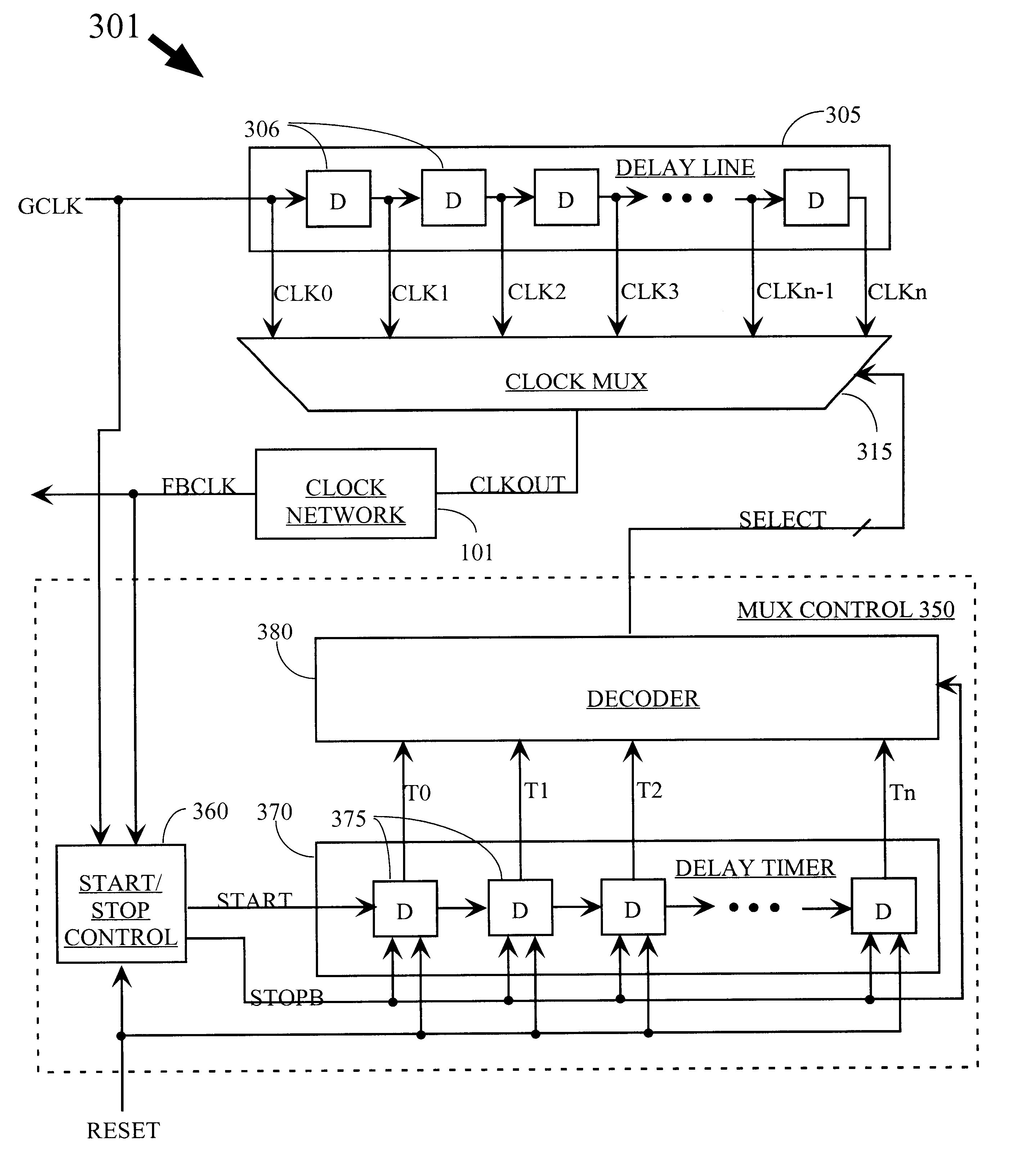
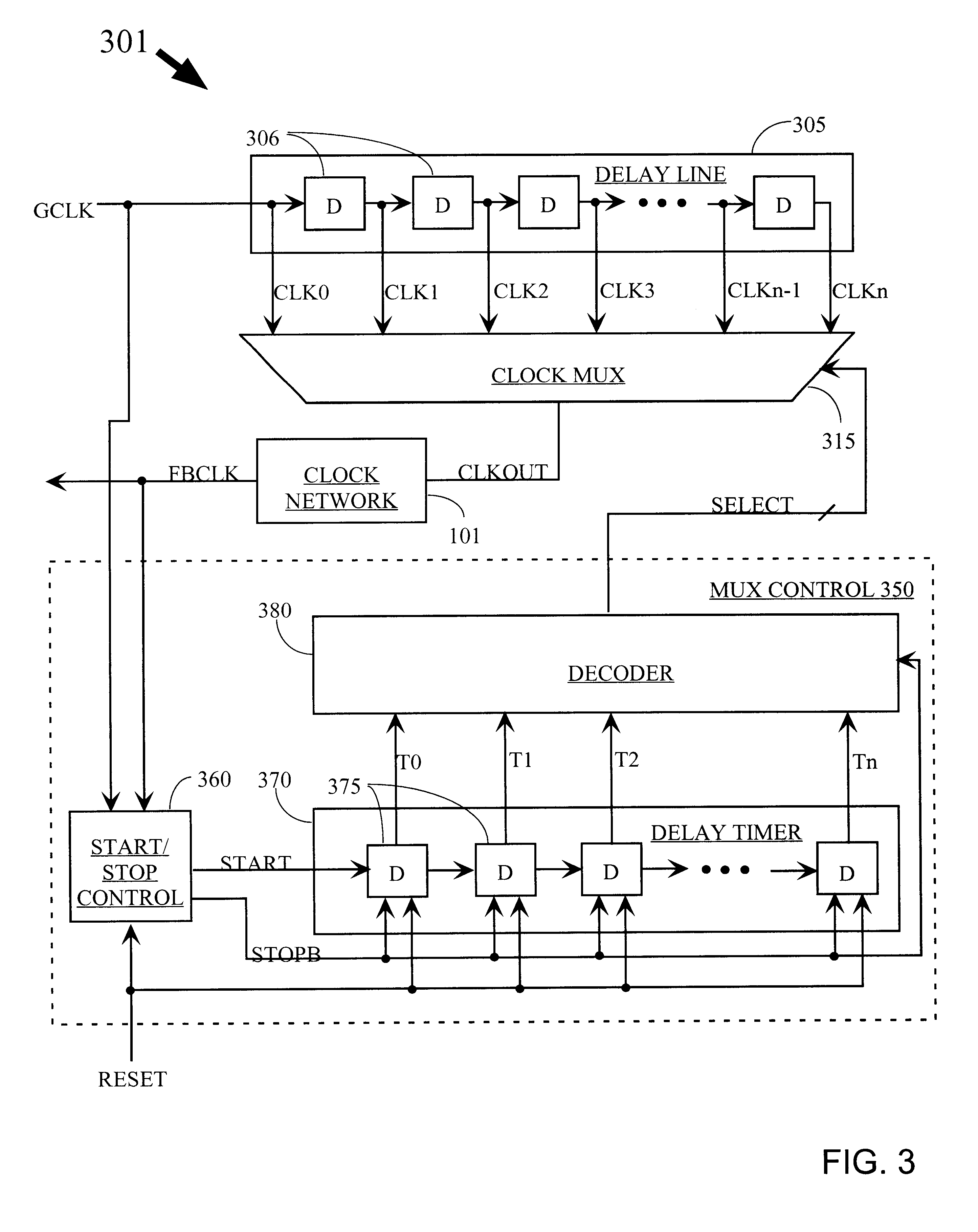
The block diagram shown in FIG. 4 is similar to that of FIG. 3, and therefore is not described in detail here, except where the embodiment of FIG. 4 differs from that of FIG. 3. However, logic blocks that were previously described only in terms of their function are shown in more detail in relation to this embodiment.

FIG. 5A is a block diagram of a Start / Stop control circuit that can be used with the embodiment of FIG. 4. Input signals to the control circuit include input clock signal GCLK, feedback clock signal FBCLK, and an enable / disable control signal DLL_ENB, whic...


PUM


Abstract

A delay-lock loop (DLL) circuit and method that accept an input clock signal and a feedback clock signal, and provide the necessary additional delay to synchronize the feedback clock signal to the input clock signal. Unlike previous circuits and methods, a single synchronization step is sufficient, provided that the frequency of the input clock signal is stable. A circuit according to the invention includes an input clock terminal supplying an input clock signal, and a delay line driven by the input clock signal and supplying a plurality of intermediate clock signals delayed from the input clock signal by incremental unit delays. A clock multiplexer selects from among these intermediate clock signals, under control of a multiplexer control circuit, the clock signal that provides the necessary additional delay to synchronize the feedback clock signal to the input clock signal. The output clock signal from the clock multiplexer is distributed through the clock network to provide the distributed clock signal as well as the feedback clock signal.

Description

The invention relates to integrated circuits (ICs). More particularly, the invention relates to a delay-lock loop (DLL) circuit and method for an IC.Clock signals are used in virtually every IC and electronic system to control timing. For example, every time there is a rising edge on a clock signal, all the flip-flops in a circuit may change state. Clearly, clocks are often heavily loaded signals, and may be bussed throughout a very large IC. Even with specially-designed global buffers, there is typically a delay between the clock edge received by the IC at the pad, and the clock edge received by the last-served flip-flop on the IC (i.e., between the "input clock signal" and the "destination clock signal"). This delay, designated herein as t.sub.d, may cause difficulties in interfacing between ICs, or simply slow down the overall system speed. Input data may be provided in synchronization with the input clock signal, while output data is typically provided in synchronization with th...

Claims


Application Information

Patent Timeline
IPC IPC(8): H03L7/085H03L7/081H03K5/13H03L7/08H03K5/00
CPCH03K5/00006H03K5/131H03K5/133H03L7/085H03L7/0814
Inventor NGUYEN, ANDY T.
Owner XILINX INC
Why Eureka
Try Eureka