Implant with composite coating

Inactive Publication Date: 2001-07-17
SHALBY ADVANCED TECH INC
View PDF21 Cites 208 Cited by
  • Summary
  • Abstract
  • Description
  • Claims
  • Application Information

AI Technical Summary

Problems solved by technology

A problem with this technology has been that the best substrate materials are not the best materials to be in contact with living tissue.
However, a disadvantage of this approach is that biocompatible materials are often soft or brittle.
Another disadvantage of this approach has been relatively high cost and/or technical complexity.
Heretofore, the requirements of go

Method used


Image

  • Implant with composite coating
  • Implant with composite coating
  • Implant with composite coating

Examples


Embodiment Construction

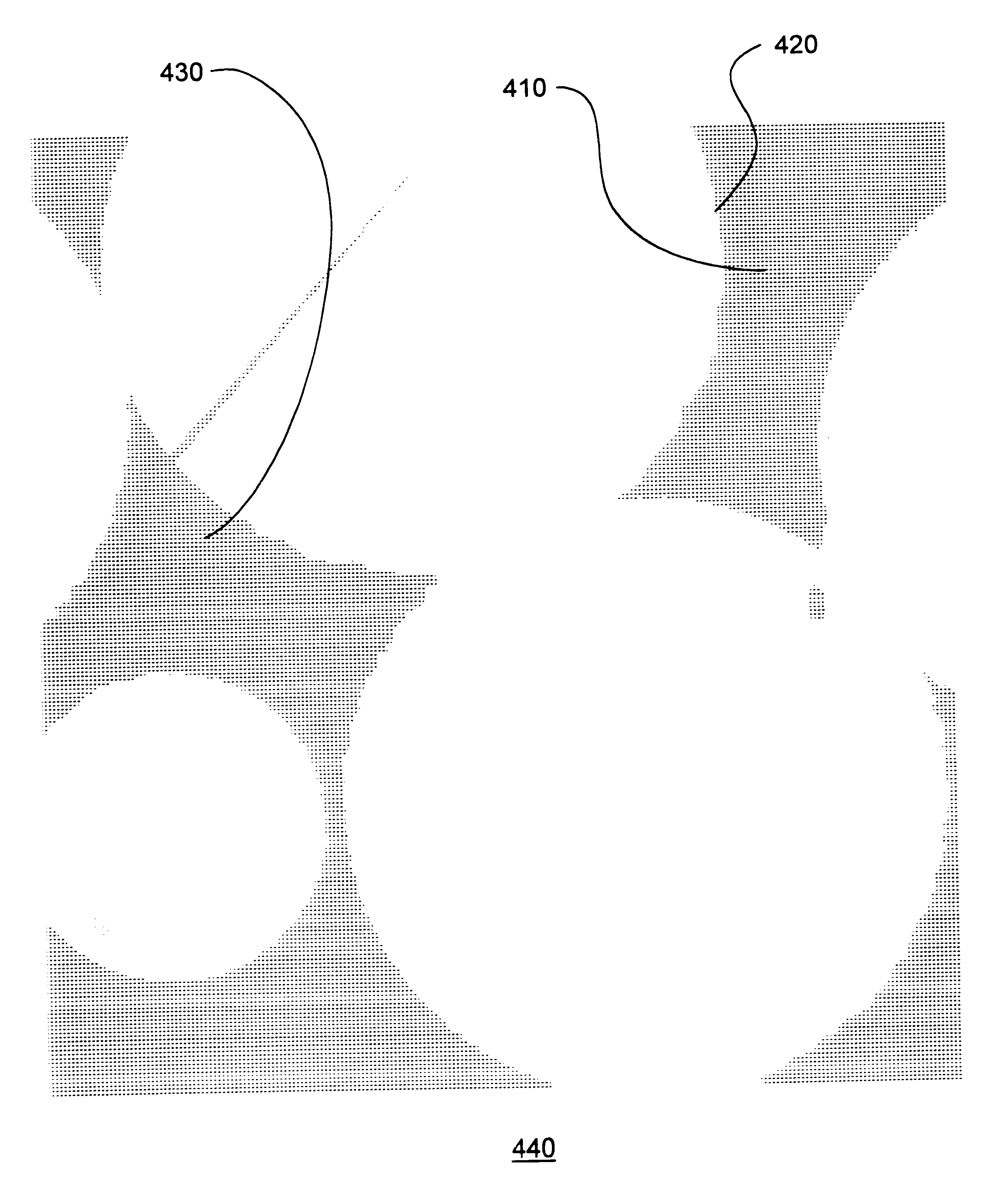
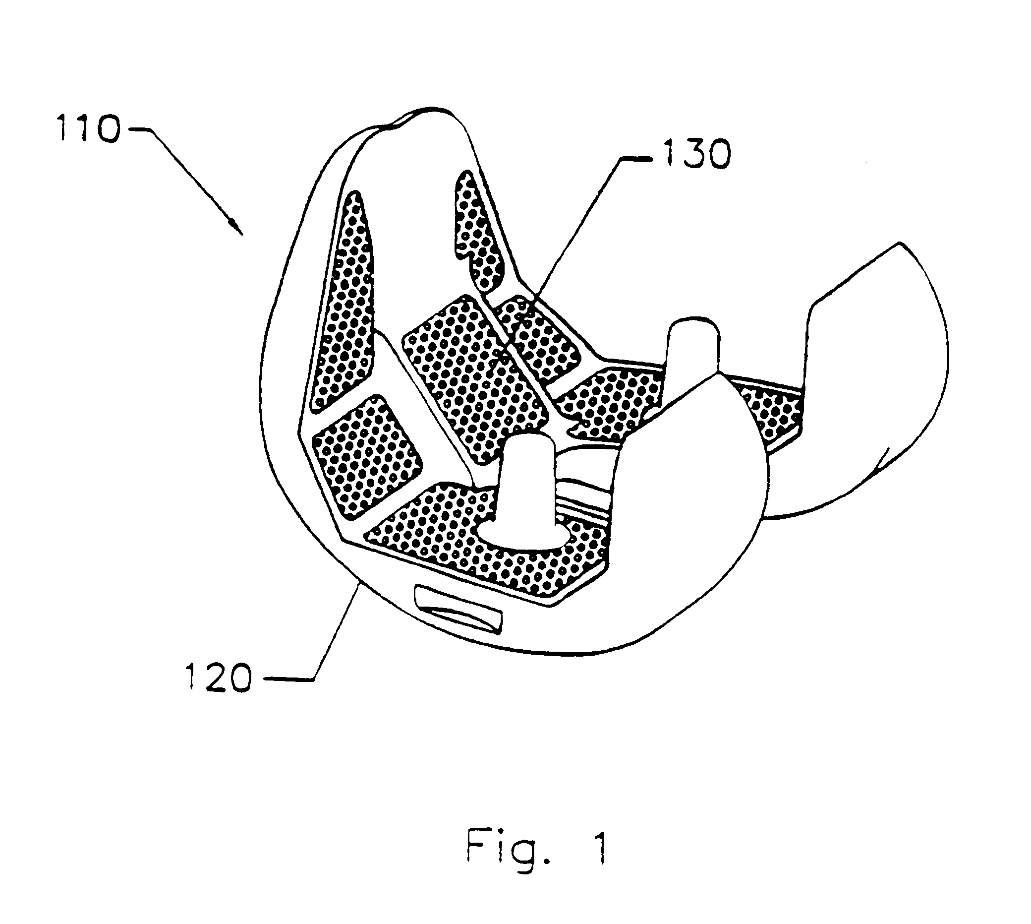
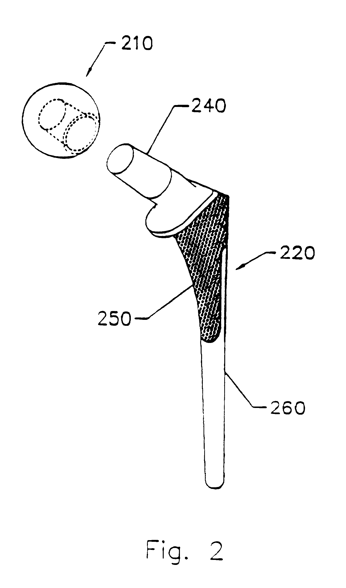
The invention and the various features and advantageous details thereof are explained more fully with reference to the nonlimiting embodiments that are illustrated in the accompanying drawings and detailed in the following description. Descriptions of well known components and processing techniques are omitted so as not to unnecessarily obscure the invention in detail.

The context of the invention is providing an implant to be positioned in vivo during surgery, especially orthopedic surgery to replace a joint, such as, for example, a knee joint or a hip joint. Thus, the implant can be used in a method for orthopedic surgery that includes surgically positioning the implant within a vertebrate in need thereof If bone growth is facilitated, the implant can be termed part of an osteoconductive process that includes contacting a bone under in vivo conditions with the implant.

Referring to the drawings, a detailed description of preferred embodiments of the invention is provided with respec...


PUM

PropertyMeasurementUnit
Compositionaaaaaaaaaa
Stabilityaaaaaaaaaa
Biocompatibilityaaaaaaaaaa

Abstract

Systems and methods are described for implants with composite coatings to promote tissue in-growth and/or on-growth. An implant includes: a substrate; a structured surface formed on at least a portion of the substrate; and a biocompatible coating deposited on at least a fraction of the structured surface. The systems and methods provide advantages in that the implant has good biocompatibility while the biocompatible coating has good strength.

Description

1. Field of the InventionThe invention relates generally to the field of in vivo implants. More particularly, preferred embodiments of the invention are directed to an orthopedic prosthesis having a composite coating to promote tissue in-growth and / or tissue on-growth.2. Discussion of the Related ArtPrior art implants are known to those skilled in the art. For example, conventional implants are typically composed of stainless steel, cobalt-chrome, or titanium alloy.A problem with this technology has been that the best substrate materials are not the best materials to be in contact with living tissue. Therefore, what is required is a solution that can provide a biocompatible coating on a substrate.One approach in an attempt to solve the above-discussed problems involves simply coating an implant substrate with a biocompatible material. However, a disadvantage of this approach is that biocompatible materials are often soft or brittle.Another disadvantage of this approach has been rela...

Claims


Application Information

Patent Timeline
IPC IPC(8): A61F2/30A61L27/00A61L27/30A61F2/00A61F2/38A61F2/36
CPCA61F2/30767A61L27/306A61F2/30965A61F2/36A61F2/3662A61F2/367A61F2/3859A61F2002/30016A61F2002/30906A61F2002/30925A61F2002/30929A61F2002/30968A61F2002/3097A61F2002/3098A61F2002/30981A61F2002/3611A61F2002/3625A61F2002/3631A61F2002/365A61F2250/0019A61F2310/00017A61F2310/00023A61F2310/00029A61F2310/00131A61F2310/00179A61F2310/00407A61F2310/00485A61F2310/00491A61F2310/00538A61F2310/00544A61F2310/00574A61F2310/0058A61F2310/00796A61F2310/00976A61F2/3094A61P19/00
Inventor DESPRES, III, ALFRED S.ELWOOD, EUGENE J.AHARONOV, ROBERT R.EHLERS, PETERANDERSEN, KNUT
Owner SHALBY ADVANCED TECH INC
Why Eureka
Try Eureka