Ink-jet printer head and ink spraying method for ink-jet printer

a technology of ink spraying and printer head, which is applied in the field of inkjet printers, can solve the problems of increasing the refresh cycle time, reducing the operational life of the head, and concomitant reducing performance and print quality

Inactive Publication Date: 2001-08-07
S PRINTING SOLUTION CO LTD
View PDF9 Cites 2 Cited by
  • Summary
  • Abstract
  • Description
  • Claims
  • Application Information

AI Technical Summary

Problems solved by technology

First, when forming bubbles with the super-heat so as to spray the ink onto print media, the composition of the ink may be changed by the heat, and a shock wave, created by the generation and breaking of the ink bubbles, deleteriously affects the internal components of the head, with a concomitant reduction in performance and print quality.
Second, as the ink adheres to the resistor layer and the two electrodes, the ink interacts electrically with the two electrodes, and, accordingly, corrosion occurs by ion exchange at each boundary layer of the heating portions and two electrodes, thus reducing the operational life of the head.
Third, the shock wave, created by the generation of ink bubbles in ink barrier containing the ink, causes an increase in the refresh cycle time.
Fourth, the ink drop's straight-forwardness and roundness, and the uniformity in the amount of ink discharged--all of which affect the print quality--depend on the shape of the ink drop.
The manufacturing process becomes complicated, thereby increasing the production costs as the multilayer protective layers are formed over the electrodes and resistor layer.
Thus, when the voltage is applied to each electrode, it is difficult to achieve a concentration of electric current density that is satisfactory, thus necessarily requiring high voltages.
The nozzle plate, having two electrodes and a nozzle, must be formed thick, and the time required to manufacture nozzle plate is long, thus increasing the overall production costs.

Method used


Image

  • Ink-jet printer head and ink spraying method for ink-jet printer
  • Ink-jet printer head and ink spraying method for ink-jet printer
  • Ink-jet printer head and ink spraying method for ink-jet printer

Examples


Embodiment Construction

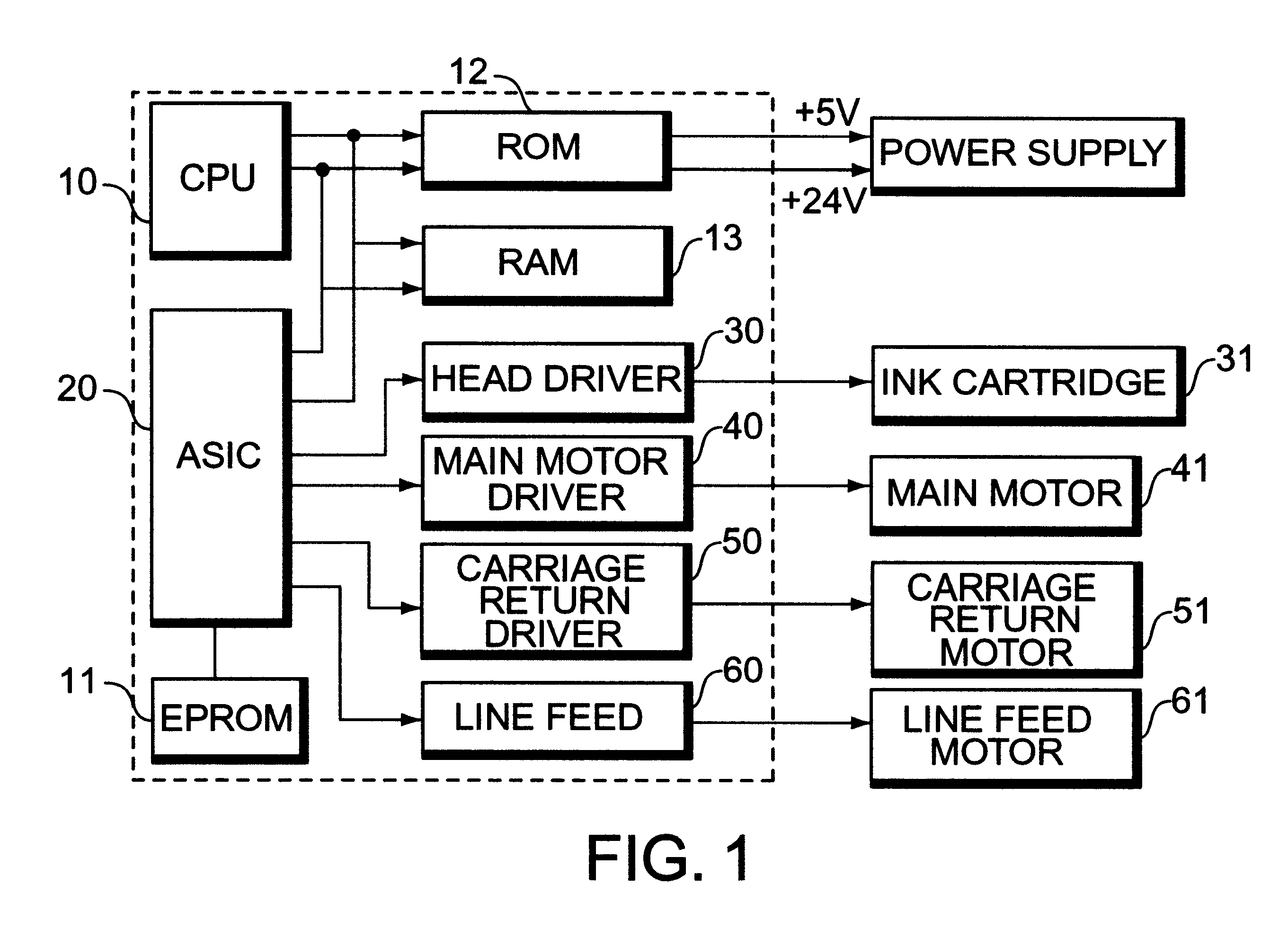
Turning now to the drawings, the construction and operation of an electronic circuit for controlling operation of an ink-jet printer is illustrated by FIG. 1. Central processing unit (CPU) 10 that receives signals from a host computer (not illustrated) through a printer interface (also not illustrated), and reads a system program out of an erasable and programmable read only memory (EPROM) 11 that stores values initially set for the printing operation and various items of information necessary for operation of the printing system, and then executes the program in order to produce a control signal in accordance with the program. Read only memory (ROM) 12 holds programs for controlling the printer, and random access memory (RAM) 13 temporarily stores data used during operation of the system.

The control circuit has an application-specification integrated circuit (ASIC) 20 that transmits data from CPU 10 to most of the peripheral logic ASICs necessary for the operation of the system. He...


PUM


Abstract

An ink-jet printer head is constructed with first electrodes formed on a silicon substrate on which oxidization is performed, and each having a region contacting ink to generate ink bubbles, and a region coated with insulating layers; second electrodes formed on a layer different from the first electrodes' layer, electrically isolated from the first electrodes by the insulating layers, and contacting the ink, and producing ink bubbles in the ink on receipt of electric energy; bubble chamber barriers for electrically isolating the first electrodes from the second electrodes and for constituting bubble chambers in the ink; a nozzle plate having a plurality of orifices through which the ink is sprayed on a print media; ink chamber barriers formed between the second electrodes and the nozzle plate, and leading the ink into the orifices by a steam pressure generated from the bubble chamber barriers; and ink chambers formed by the ink chamber barriers and the bubble chamber barriers, and each temporarily storing the ink introduced through ink channels.

Description

1. Field of the InventionThe present invention relates to ink-jet printers generally and, more particularly, to processes and apparatus for spraying ink from the chamber for the head of an ink jet printer and onto a printable medium.2. Discussion of Related ArtTypically, conventional ink-jet printers include a central processing unit that is driven by signals received from a host computer through printer interface, to read a system program from memory, to store values initially set for the printing operation and various information necessary for the printing system, and to then execute the system program to produce a control signal; a read only memory that holds programs for controlling the printer; and a random access memory that temporarily stores data for operation of the system. An application-specification integrated circuit transmits data from the central processing unit to most of the peripheral logic ASICs as may be necessary to execute the instructions from the central proc...

Claims


Application Information

Patent Timeline
Patent Type & Authority Patents(United States)
IPC IPC(8): B41J2/14B41J2/05B41J2/11B41J2/175
CPCB41J2/14129B41J2/11
Inventor AHN, BYUNG-SUN
Owner S PRINTING SOLUTION CO LTD
Why Eureka
Try Eureka