Collision warning system

Inactive Publication Date: 2001-08-14
QINETIQ LTD +1
View PDF11 Cites 79 Cited by
  • Summary
  • Abstract
  • Description
  • Claims
  • Application Information

AI Technical Summary

Problems solved by technology

a. false alarms from vehicles in adjacent lanes and "road furniture" (street signs, lamp standards etc.);
b. mutual interference between radar systems;
c. reliably discriminating vehicles and structures which are a potential hazard from those which are not an immediate safety threat; and
d. producing a cost-effective hardware configuration which will cope with the above problems
The signal processing capability required to cope with such an obstacle rich environment is considerable and adds to the complexity and expense of such systems.
This system has a disadvantage that a commutator is required for switching the antennae which adds to cost of the system.
A problem with the systems described in German patent specification number DE 27 34 998 and European Patent Application number EP 0 658 775 A is that only a single antenna receives radiation reflected from the scene at any particular time.
This may result in a situation where the ob

Method used


Image

  • Collision warning system
  • Collision warning system
  • Collision warning system

Examples


Embodiment Construction

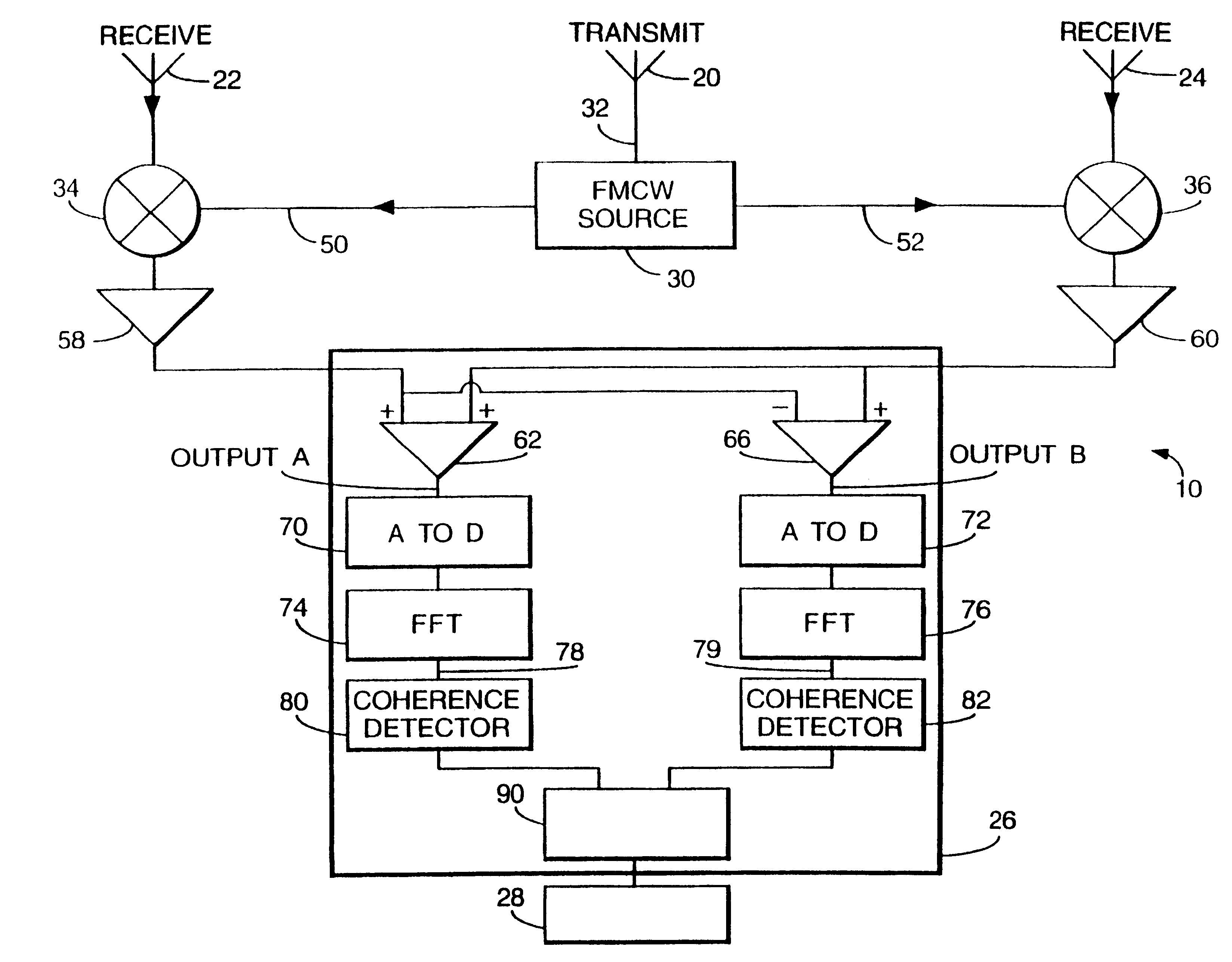
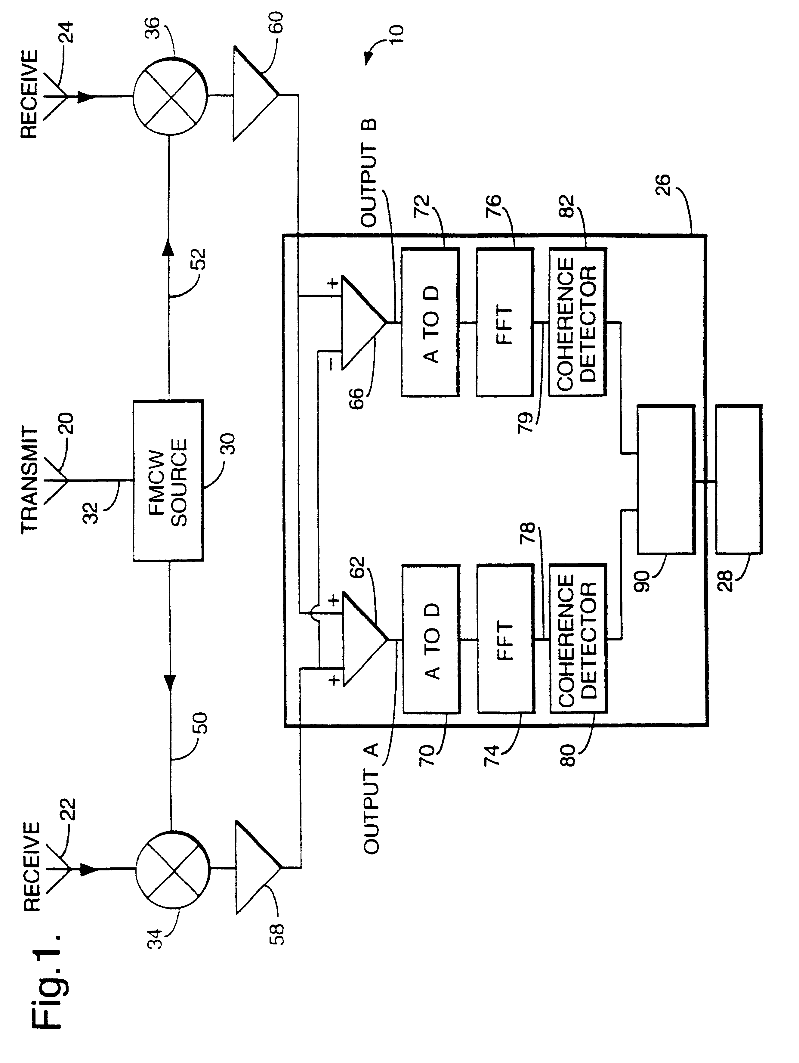
Referring to FIG. 1 there is shown a collision warning radar system indicated generally by 10 which would be mounted on a vehicle. The system 10 includes a microwave transmit antenna 20, two microwave receive antennas 22 and 24, and a signal processor 26 connected to a warning buzzer 28. The microwave transmit antenna 20 is a conventional waveguide horn emitting microwave radiation having a frequency in the range 76 to 77 GHz. The transmit antenna 20 produces a radar beam which is 10.degree. wide in azimuth. The radar beam is a transmitted signal which is a single sweep linear frequency modulated continuous wave (FMCW) signal, as described by Stove in the previously referenced article. The FMCW signal is generated by a source 30 and passed to the transmit antenna 20 via a transmission line 32. The receive antennas 22 and 24 are separated laterally by a distance of 1.2 meters and are each a horn type antenna having an angle of sensitivity of 10.degree. to match the beamwidth of the t...


PUM


Abstract

A collision warning system (10) discriminates between objects which pose a threat of collision from those which do not by measuring the relative sightline rate of the object, this being a measure of the rate of change of angular position of the object if the sightline rate is above a threshold value, there is little risk of collision. To measure the sightline rate, a radar source (20) emits microwave frequency radiation which is received by two detectors (22 and 24) after reflection from a target. Signals from the detectors are processed by processing means (26). The processing means determines if the sightline rate of an object is below a certain threshold. If it is, and the relative velocities of the object and the system are such that a collision is likely, a warning buzzer (28) sounds.

Description

1. Field of the InventionThe present invention relates to a system for providing a collision warning.2. Discussion of Prior ArtThere is currently world-wide interest in the production of systems for providing a vehicle collision warning. Projected capabilities range from relatively simple "intelligent cruise control" systems, to more complex systems capable of searching the road ahead and alerting / acting on the presence of a potential hazard. For all weather performance, particularly in dense fog, a radar sensor is particularly beneficial.Considerable problems must be overcome before a truly cost-effective radar based system can be produced. Particularly important problems of implementation are:a. false alarms from vehicles in adjacent lanes and "road furniture" (street signs, lamp standards etc.);b. mutual interference between radar systems;c. reliably discriminating vehicles and structures which are a potential hazard from those which are not an immediate safety threat; andd. prod...

Claims


Application Information

Patent Timeline
IPC IPC(8): G01S13/00G01S13/93G01S7/03G01S13/34G01S13/87G01S7/288G01S7/285G01S13/931
CPCG01S7/032G01S13/931G01S13/34G01S2007/2883G01S13/87G01S7/2883G01S13/93
Inventor DEAN, MICHAELHODGES, ROBERT D
Owner QINETIQ LTD
Why Eureka
Try Eureka