System and method for non-invasively monitoring hemodynamic parameters

a hemodynamic parameter and non-invasive technology, applied in the field of systems and methods for non-invasive monitoring of hemodynamic parameters, can solve problems such as immediate blood pressure measurement, tissue damage, and even death, and achieve the effects of preventing future blood pressure from rising

Inactive Publication Date: 2001-08-28
RAMOT UNIV AUTHORITY FOR APPLIED RES & INDAL DEVMENT
View PDF25 Cites 127 Cited by
  • Summary
  • Abstract
  • Description
  • Claims
  • Application Information

AI Technical Summary

Problems solved by technology

In addition, prolonged reduction or loss of pressure severely limits the amount of tissue perfusion and could therefore result in damage to, or even death of, the tissue.
Often, these physiological factors and the given medications result in a situation requiring immediate blood pressure measurement, and corrective action.
However, this technique is slow, subjective in nature, requires the intervention of a skilled clinician and does not provide the timely readings frequently required in critical situations.
Invasive methods suffer from several inherent limitations including the risk of embolization, nerve damage, infection, bleeding and vessel wall damage.
The noninvasive cuff method does not have the inherent disadvantages of the invasive technique, however it also does not provide the continuous beat-to-beat pressure variations obtainable with the invasive method.
When fast acting medications are administered, this is an inordinately long amount of time to wait for an updated pressure reading.
Also, frequent cuff inflation over extended periods of time may result in ecchymosis and/or nerve damage in the area underlying the cuff.
There are several major disadvantages to this technique.
During surgery for example, the device cannot differentiate between changes in photoplethysmograph amplitude due to intra-arterial pressure changes and those due to arterial wall compliance changes.
Consequently, the FINAPRES system cannot accurately respond to pressure changes caused by changes in vasomotor tone.
In additi

Method used


Image

  • System and method for non-invasively monitoring hemodynamic parameters
  • System and method for non-invasively monitoring hemodynamic parameters
  • System and method for non-invasively monitoring hemodynamic parameters

Examples


example 1

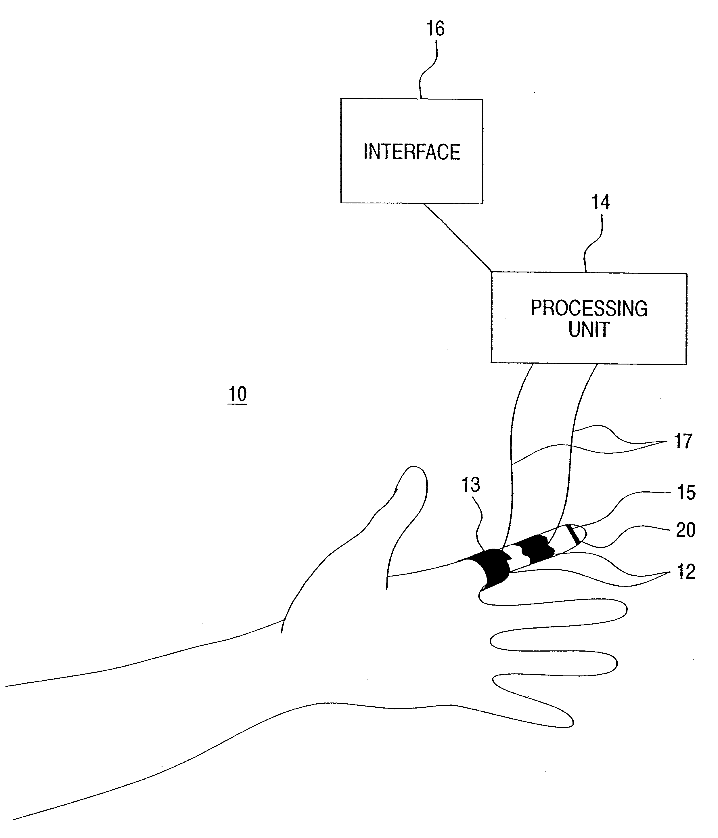
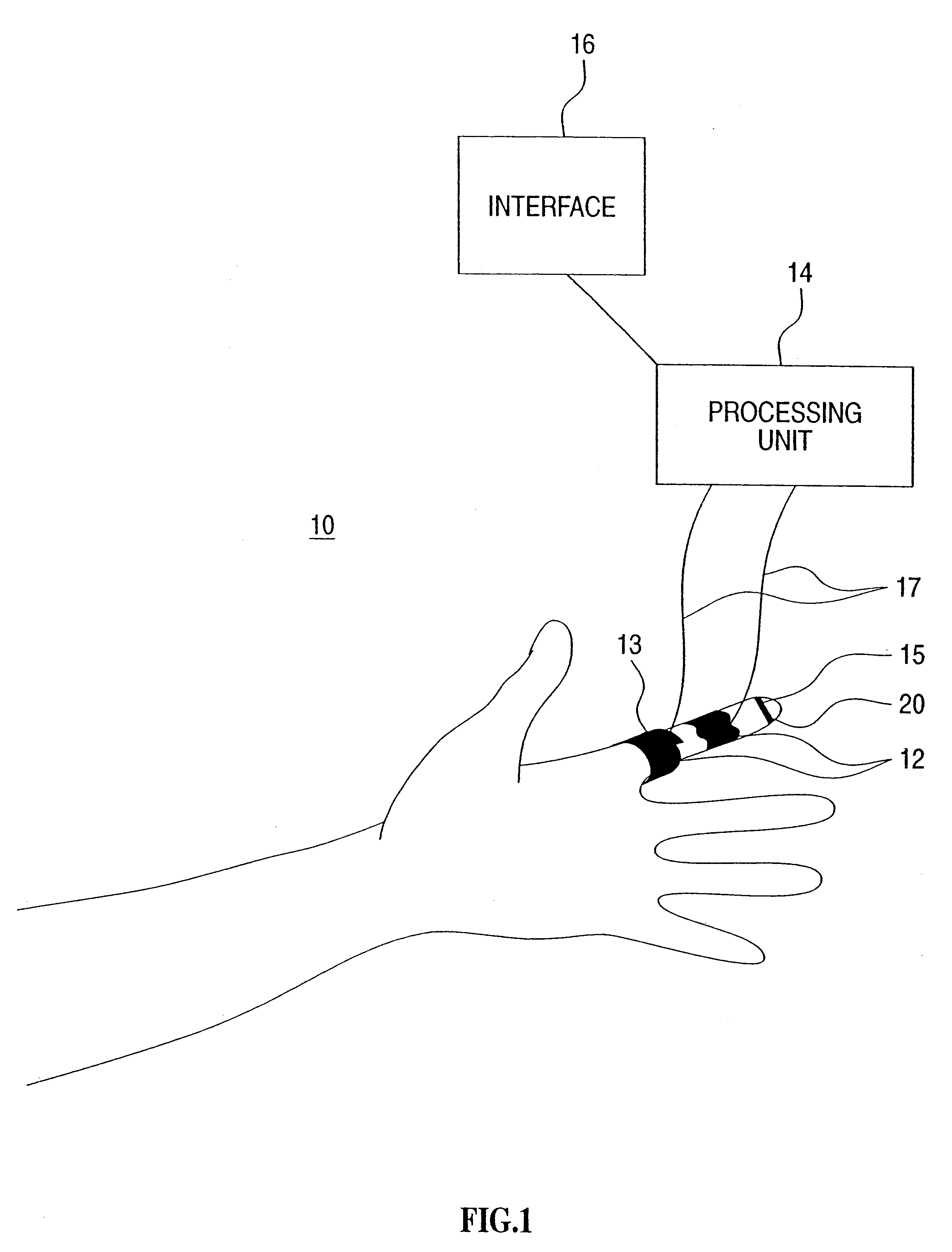
General Outline of the Method of the Present Invention

The present invention utilizes two or more photoplethysmograph detectors to collect infrared signal data from blood vessels underlying the skin.

In order to process the signals resultant from the photoplethysmograph detectors (PPG detectors or PPGs) into values useful for determining parameters such as, for example, blood pressure, blood viscosity, blood density, blood vessel radius and blood vessel elasticity, the following general steps are performed.

(i) A low pass filter (.about.250 Hz) is used to remove noise from the signals generated by from the PPG detectors.

(ii) The beginning and end of a heart beat are detected by finding the local minimum points of the PPG signals.

(iii) The signals from each PPG detector are divided into separate segments, each segment being reflective of a single heart beat. Segments from the PPGs corresponding to the same heart beat are co-analyzed.

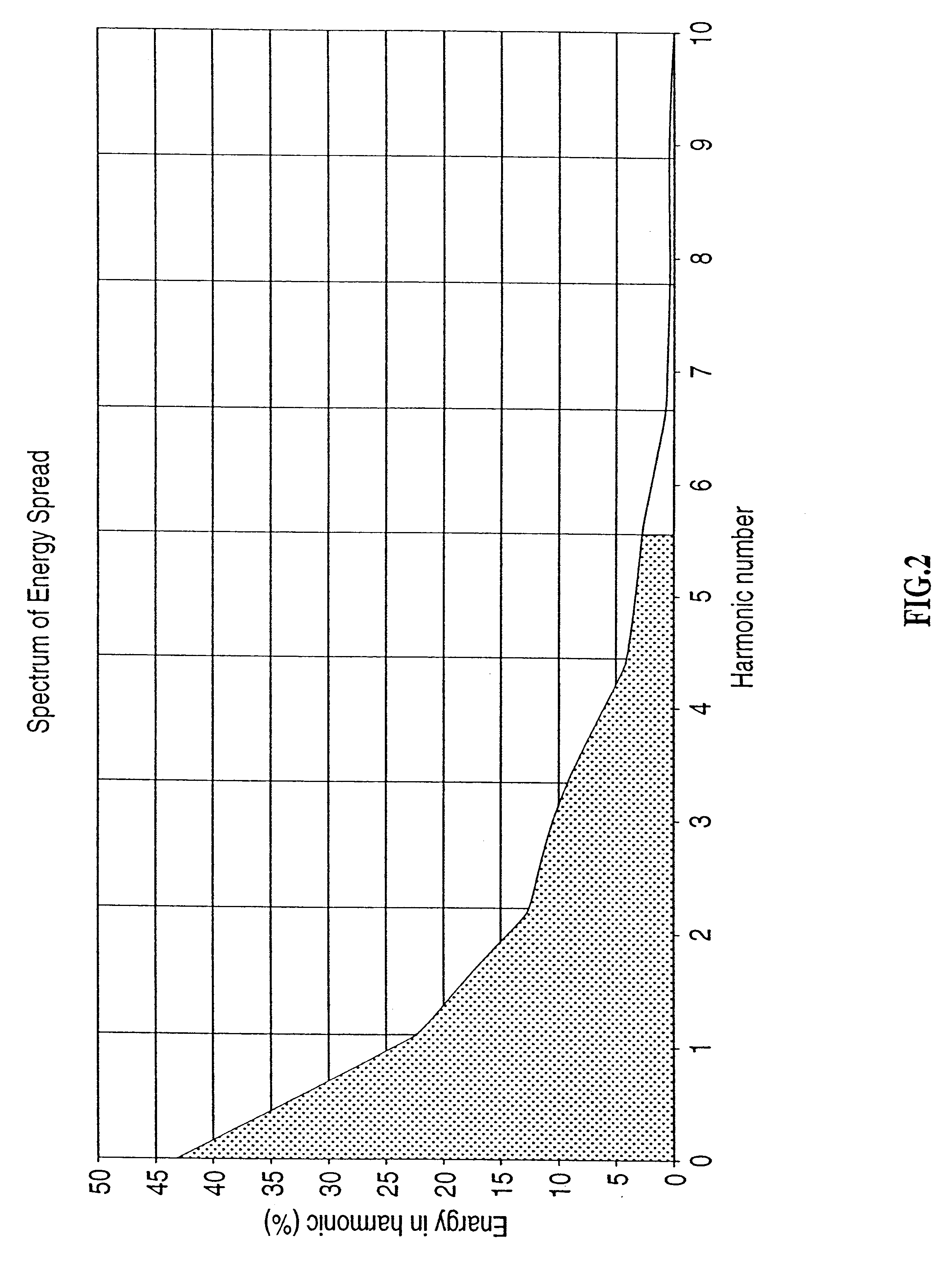
(iv) A fast Fourier transform (FFT) is performed for e...

example 2

The IRC Method

The following Equations are utilized in order to determine parameters associated with blood flow in a blood vessel according to preferred embodiments of the present invention.

A model of a blood vessel is represented in FIG. 5.

The following Equations describe the amplitude of the blood volume signals (.eta..sub.1, .eta..sub.2) measured by the two PPG detectors, as a function of the forward wave amplitude (A.sub.n).

In all the Equations below n indicates the harmonic number. Each of the Equation is then used for n=1 . . . 6. ##EQU1##

The above pair of Equations can be reduced to a single Equation without the dependence on the forward wave amplitude (A.sub.n): ##EQU2##

Equation 2 can be rearranged in order to reflect the dependence on ##EQU3##

The reflection coefficient can be described by the following Equation (4) assuming that .gamma..sub.n has only a real value: ##EQU4##

Due to the fact that the phase difference between the forward propagated wave on the two detectors is s...

example 3

Results

Calculating R, .beta., C.sub.0 :

Table 1, and FIGS. 8-10 respectively, represent the results obtained for R, .beta., C.sub.0 using the Equations described under Example 2. The values for C.sub.0 were obtained prior to a calibration process and therefor are accurate only within a linear range of C.sub.0. The values for R were calculated while assuming a known value for .nu. (for blood, .nu.=0.0381 cm.sup.2 / sec) and are presented only to show the correlation with vivo measurements.

Calculating a Continuous Blood Pressure:

Calculating a continuous blood pressure requires calculating the systolic and diastolic blood pressure and calculating the waveform of the continuous blood pressure signal.

Calculating the systolic and diastolic blood pressure for each heart beat can be achieved by using the Hill Equation ("cardiovascular fluid dynamics"--Uri Dinnar, CRC Press, 1981) and further by assuming (i) that in a blood vessel there is a linear correlation between stress and strain (.sigma...


PUM


Abstract

A system for non-invasively monitoring at least one hemodynamic vascular parameter of an individual is disclosed. The system comprises (a) at least two infrared detectors being positionable in a spaced apart configuration against a region of a skin of the individual above at least one blood vessel, each of said at least two infrared detectors being for individually collecting infrared spectral data from said region of the skin, said infrared spectral data corresponding to a volume of blood present within said at least one blood vessel; and (b) a processing unit being in communication with said at least two infrared detectors, said processing unit being for independently processing said infrared spectral data collected by each of said at least two infrared detectors so as to yield information pertaining to the at least one hemodynamic vascular parameter of the individual.

Description

FIELD AND BACKGROUND OF THE INVENTIONThe present invention relates to a system and method for monitoring hemodynamic vascular parameters of a patient and, more particularly, to a system and method utilizing photoplethysmography to monitor parameters associated with, for example, blood pressure and blood flow of a patient.Hemodynamic vascular parameters such as blood pressure, blood flow and the like which are typically measured using non-invasive procedures are routinely monitored by physicians in order to determine the physiological state of the heart and circulatory system of a patient. Of these hemodynamic vascular parameters, blood pressure is the most commonly monitored.Blood pressure is the force within the circulatory system of an individual that ensures a flow of blood and delivery of oxygen and nutrients to the tissue.Abnormal blood pressure readings and / or blood pressure fluctuations over time are oftentimes indicative of heart or circulatory disorders. Hypertension is one...

Claims


Application Information

Patent Timeline
IPC IPC(8): A61B5/024
CPCA61B5/02416A61B5/6838A61B5/6826
Inventor AKSELROD, SOLANGESCHECHTER, AMIR
Owner RAMOT UNIV AUTHORITY FOR APPLIED RES & INDAL DEVMENT
Why Eureka
Try Eureka