Method and apparatus for determination of additives in metal plating baths

a technology of additives and metal plating, applied in the direction of liquid/fluent solid measurements, material electrochemical variables, instruments, etc., can solve the problems of microelectronics exceeding the capabilities of al metal, inability to conventional cvd, performance demands, etc., to achieve efficient characterization of the electroplating medium, simple operation, and economic effect of capital cost and operating expens

Inactive Publication Date: 2001-08-28
ANCOSYS
View PDF2 Cites 71 Cited by
  • Summary
  • Abstract
  • Description
  • Claims
  • Application Information

AI Technical Summary

Benefits of technology

to provide an improved system for determination of organic additive concentration in a copper electroplating bath, that is simple in operation, economic in capital cost and operating expense, and efficient in characterization of the electroplating medium.
In one embodiment of the present invention, the reference electrode resides in a reference chamber that is physically and electrically isolated from the mixing chamber that houses the test electrode (upon which Cu is deposited). The reference electrode is continuously immersed in the base copper plating electrolyte solution. By never exposing it to the variously doped bath solutions in the mixing chamber, the reference electrode need not be cleaned following each plating / measurement cycle. Thus, it remains continuously "equilibrated" to the base copper plating electrolyte solution, and the equilibration step is reduced to the time necessary for the test electrode to "equilibrate" to a fresh base copper plating electrolyte solution. This reduces the equilibration step by roughly an order of magnitude over the prior art, i.e., to approximately two minutes.
The reference chamber is connected in fluid flow relationship to the mixing chamber by a capillary tube, whose mixing chamber terminal end is in close physical proximity to the plating surface of the test electrode. By this arrangement, the apparatus of the present invention achieves several additional advantages, including:
Potential difference (iR drop) across the electrolyte is eliminated or dramatically reduced.
The flow of base copper plating electrolyte solution through the capillary tube and against the plating surface of the test electrode facilitates the removal of air on the test electrode, contributing to consistent cycle-to-cycle measurements.

Problems solved by technology

Despite the prior ubiquity of Al as a metalization medium, performance demands associated with increasing signal speeds and decreasing feature geometries of microelectronics have exceeded the capabilities of Al metal.
The properties of Cu are not amenable to conventional CVD metalization approaches, due in part to the lack of suitable copper source reagents, and in consequence Cu is typically deposited on the microelectronic device structure via electroplating.
Electroplating of copper, however, has various associated problems.
The plating process with an unaugmented etch solution of such type normally proceeds too rapidly.
However, the concentration of these additives is not constant, due to either "drag-out" by the wafers or by electrochemical reaction and loss during the electroplating.
Accurate, real-time measurement of these electroplating bath additive concentrations, necessary for quality control, has been problematic.
This circumstance makes normal analytical procedures difficult to effectively apply, due to the masking effect of the high concentration of inorganic bath components (copper, acid, etc.).
Hence, an entire concentration determination sequence can require a considerable period of time to complete.
Any significant depletion of organic additives during the determination will render the analytical method useless.

Method used


Image

  • Method and apparatus for determination of additives in metal plating baths
  • Method and apparatus for determination of additives in metal plating baths
  • Method and apparatus for determination of additives in metal plating baths

Examples


example

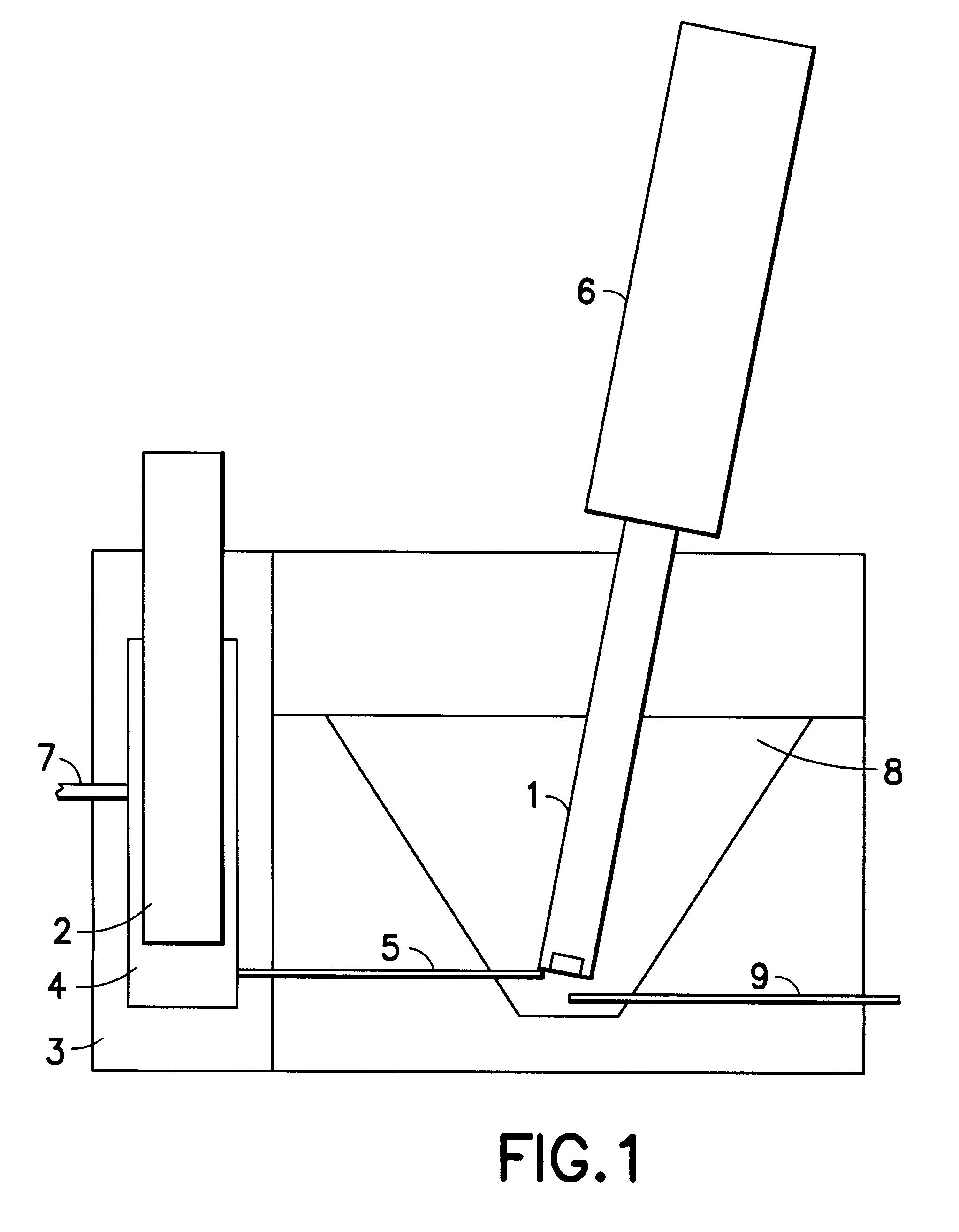
In addition to the measuring vessel described above, the analyzer consists of 4 digital burettes that are filled with the following solutions:

Burette 1: the sample itself collected from an overflow sample capture vessel

Burette 2: diluted (25.times.) accelerator additive

Burette 3: diluted (25.times.) suppressor

Burette 4: the base solution composed of

70 g / l cupric sulfate pentahydrate

180 g / l 95-97% sulfuric acid

60 ppm chloride as hydrochloric acid

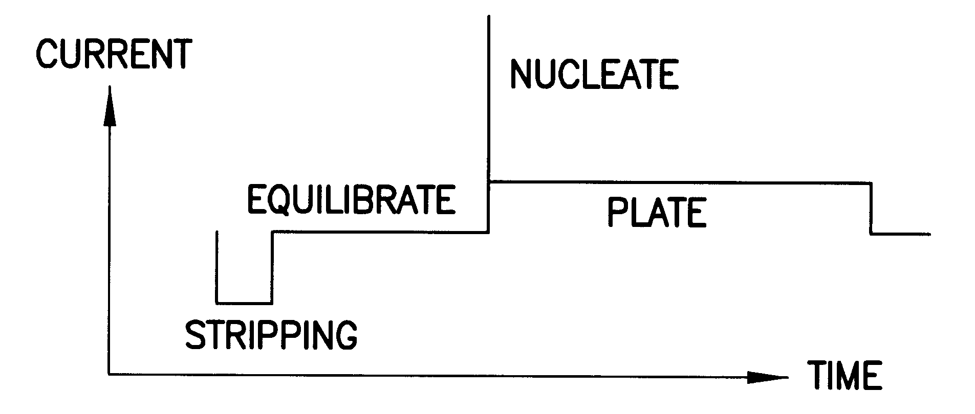
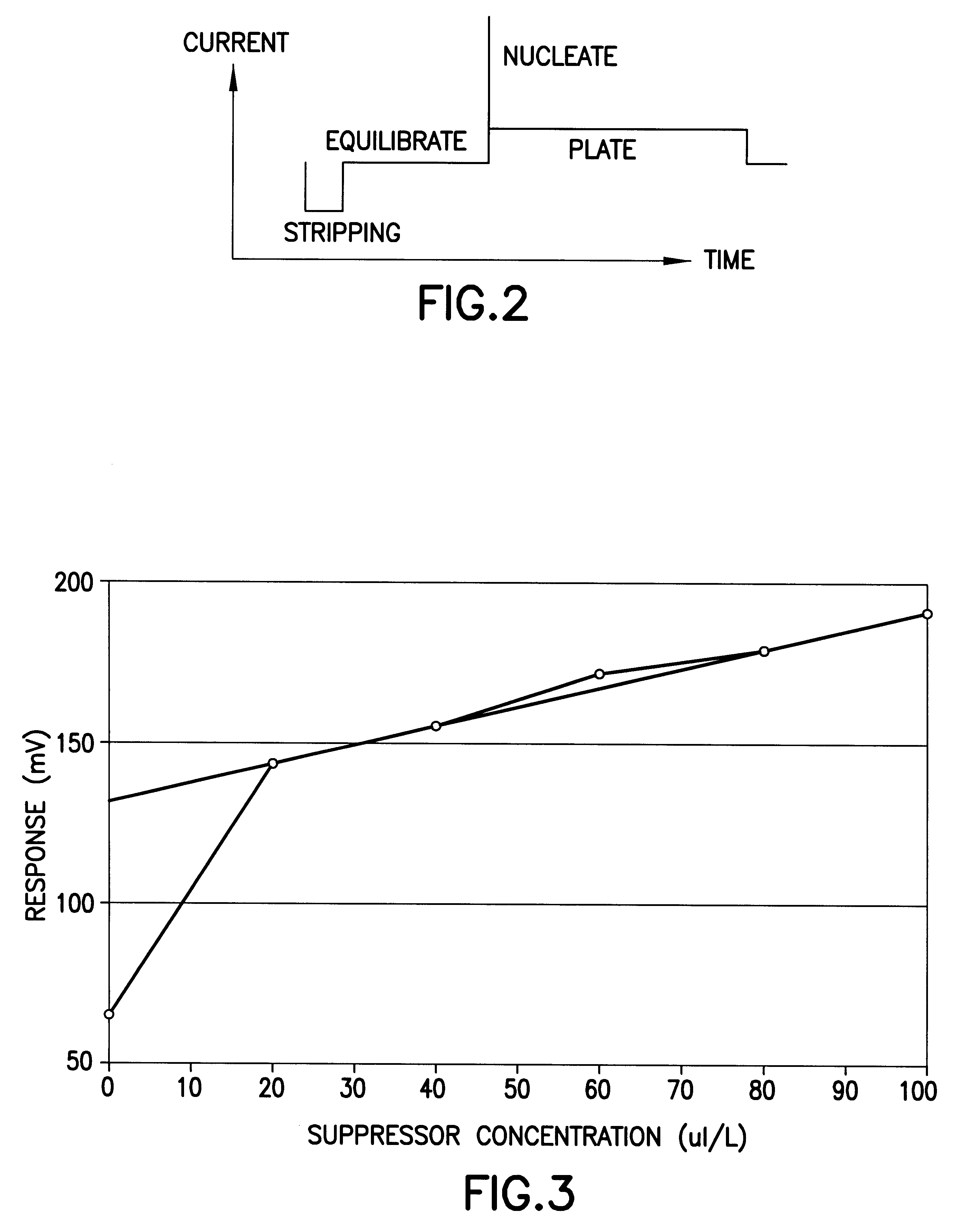
The analyzer was programmed to perform the following sequence. The overall operation given in terms of the actual command code used on the analyzer was as follows:

This sequence of commands has the following significance: 1 C3 a pre-analysis step to prime the dispensing tip of burette 3 by dispensing 0.1 ml

2 S20 a sampling operation in which burette 1 is filled with fresh sample and the dispensing tube (using flow segregation) with 1 ml of a 20.times.diluted sample

3 C3 the background level for the suppressor determination is raised by adding 0...


PUM

PropertyMeasurementUnit
volumeaaaaaaaaaa
volumeaaaaaaaaaa
volumeaaaaaaaaaa

Abstract

An apparatus and method for the indirect determination of concentrations of additives in metal plating electrolyte solutions, particularly organic additives in Cu-metalization baths for semiconductor manufacturing. The apparatus features a reference electrode housed in an electrically isolated chamber and continuously immersed in the base metal plating solution (without the additive to be measured). An additive concentration determination method comprises electroplating a test electrode at a constant or known current in a mixing chamber wherein the base metal plating solution is mixed with small volumes of the sample and various calibration solutions containing the additive to be measured. Plating potentials between the electrodes are measured and plotted for each of the solution mixtures, and data are extrapolated to determine the concentration of the additive in the sample. A multi-cycle method determines the concentration of both accelerator and suppressor organic additives in Cu plating solution in a single test suite.

Description

1. Field of the InventionThe present invention generally relates to the determination of additives in metal plating baths, and more specifically to a method and apparatus for determination of organic suppressor and accelerator additives in semiconductor copper electrolysis plating baths.2. Background of the InventionTraditionally, aluminum (Al) has been used as the material of choice for metalization in forming interconnect layers in the manufacture of semiconductor microelectronic integrated circuits. Al is commonly deposited on semiconductor structures by chemical vapor deposition (CVD), which allows for precise control and highly uniform deposition of the product metal-containing film.Despite the prior ubiquity of Al as a metalization medium, performance demands associated with increasing signal speeds and decreasing feature geometries of microelectronics have exceeded the capabilities of Al metal. Copper (Cu) therefore is increasingly being utilized as a semiconductor interconne...

Claims


Application Information

Patent Timeline
Patent Type & Authority Patents(United States)
IPC IPC(8): G01N27/416G01N27/42C25D21/12G01N1/00G01N27/30
CPCG01N27/42G01N27/4161G01N27/26
Inventor ROBERTSON, PETER M.
Owner ANCOSYS
Why Eureka
Try Eureka