Ceramic heater/fuser roller with internal heater

a ceramic heater and roller technology, applied in the field of ceramic heater/fuser roller with internal heater, can solve the problems of inability to adapt to present-day manufacturing and use, insufficient dielectric strength of thinner coat, and inability to meet the requirements of manufacturing and use, so as to achieve easy and straightforward bonding, less danger of damage, and faster ramp time

Inactive Publication Date: 2001-09-04
AMERICAN ROLLER
View PDF21 Cites 33 Cited by
  • Summary
  • Abstract
  • Description
  • Claims
  • Application Information

AI Technical Summary

Benefits of technology

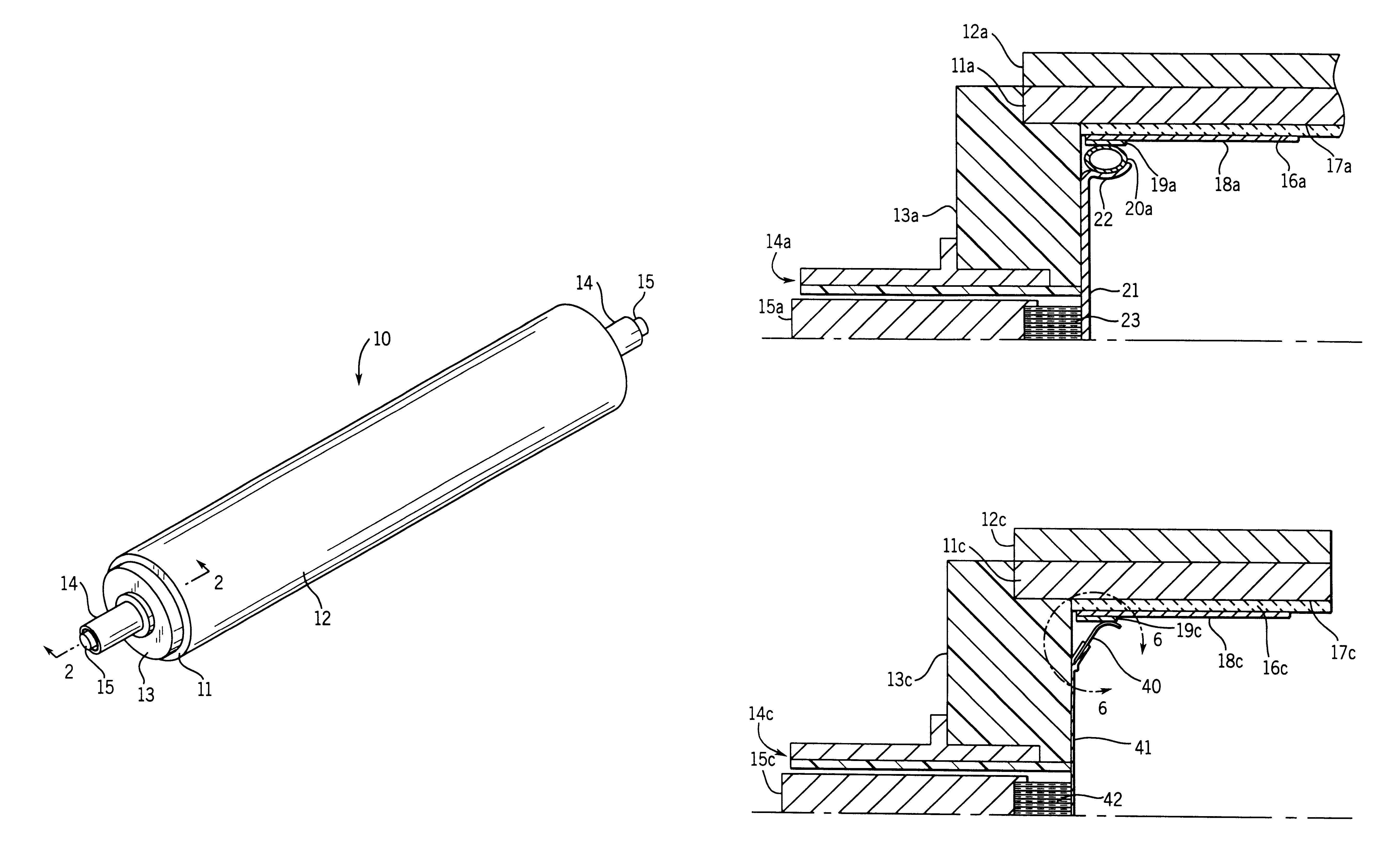
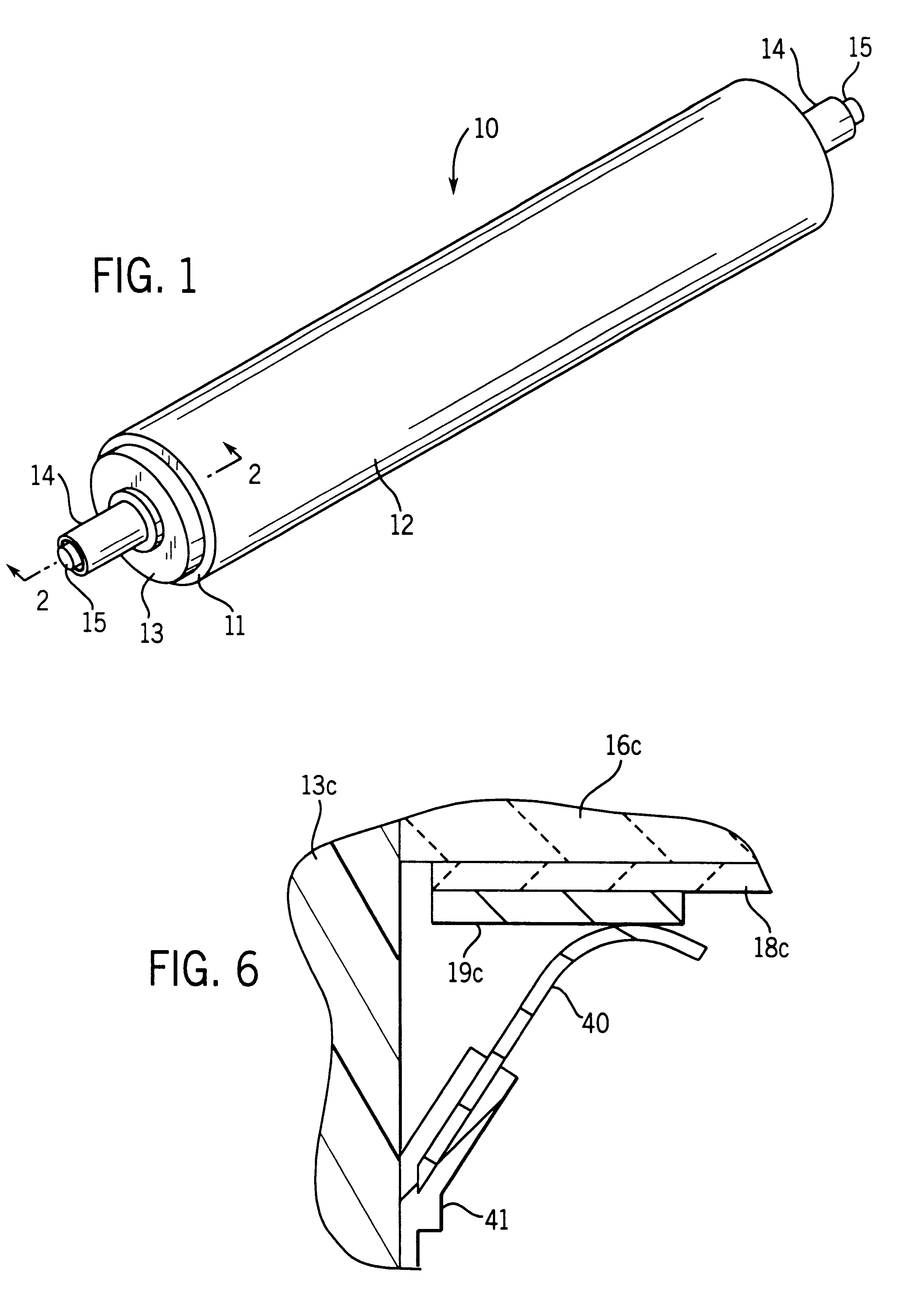
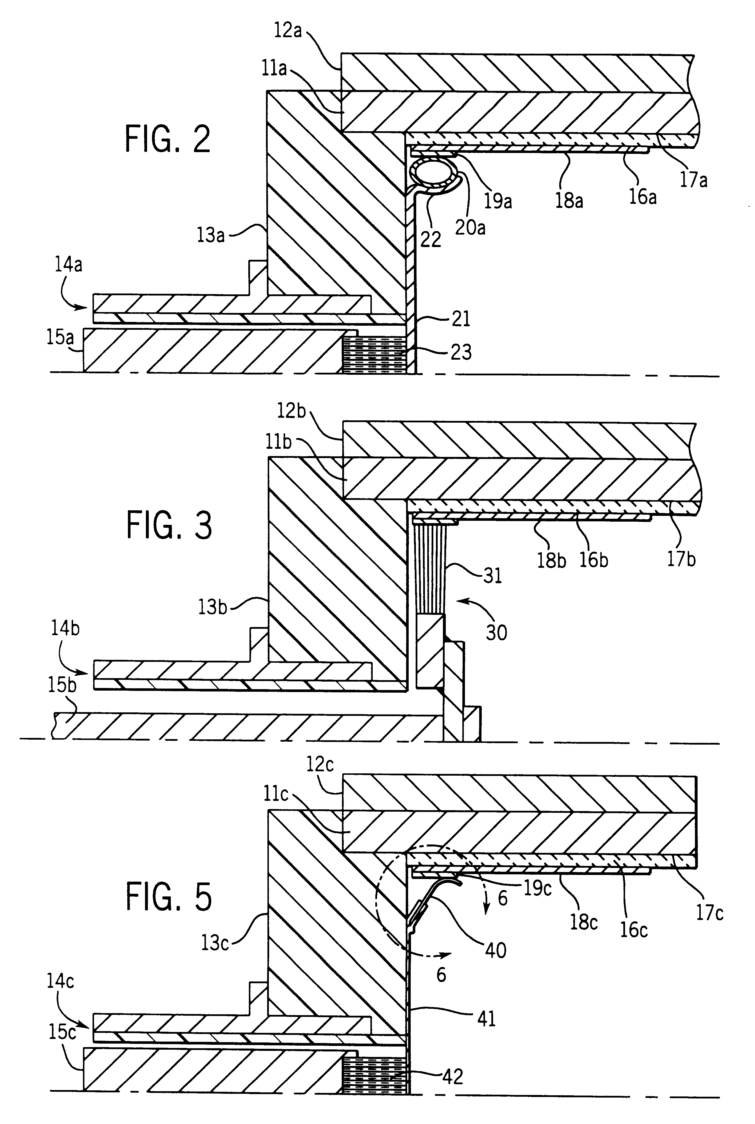
One advantage of the present invention is that it is easier and more straightforward to bond release materials to an exterior metal surface of the core 11 than to bond them to ceramic materials, especially if the release material has to be removed and replaced. If the heater is positioned inside the roller 10, there is also far less danger of damaging the heater when the release material is applied, removed, or reapplied. Another advantage is that, with the core 11 grounded, the outer surface of the roller has zero voltage and a zero shock hazard potential.
is that it is easier and more straightforward to bond release materials to an exterior metal surface of the core 11 than to bond them to ceramic materials, especially if the release material has to be removed and replaced. If the heater is positioned inside the roller 10, there is also far less danger of damaging the heater when the release material is applied, removed, or reapplied. Another advantage is that, with the core 11 grounded, the outer surface of the roller has zero voltage and a zero shock hazard potential.
The initial goal of the invention was to make a roller 10 that would rise from 70.degree. F. to 400.degree. F. in 60 seconds. One factor to be considered is the number of watts applied per pound of core material. That number is approximately 700 watts per pound for steel and 1400 watts per pound for aluminum. Steel cores tested were 3 inches in diameter.times.16 inches long with an 0.080-inch thick wall for a roller weight of 2.8 pounds. Approximately 2000 watts will raise the temperature of the roller to 400.degree. F. in 60 seconds. At 240 volts and 2000 watts, the current is 8.3 amps for a ceramic heater resistance of about 29 ohms. This results in a heater thickness of between 0.5 and 1.0 mils for this size of roller. To bring the 2.8 pound roller to 400.degree. F. in only 30 seconds, 16.6 amps at 240 volts is required. A faster ramp time can be achieved if the core weight is reduced.
Most of the rollers tested had a ramp time to 400.degree. F. in the range of 120 seconds. These were used for thermal cycle testing from the 120.degree. F. to 140.degree. F. range to the 400.degree. F. to 420.degree. F. range 9 to 10 times per hour on a continuous basis. To maximize the number of cycles per hour, the rollers were not cooled all the way to ambient after each heating cycle.

Problems solved by technology

This is inefficient and requires higher temperature at the lamp surface to transfer heat for a given power level, than does heat transfer by conduction.
The designs in these patents are complex and not readily adapted to present day manufacturing and use.
A thinner coat may not have sufficient dielectric strength, while a thicker coat decreases thermal conduction.
Alumina can be used as an insulator but may crack at temperatures above 500.degree. F. on steel cores.
Zirconia does not readily crack on steel or aluminum, but may be subject to dielectric failure above 700.degree. F.

Method used


Image

  • Ceramic heater/fuser roller with internal heater
  • Ceramic heater/fuser roller with internal heater
  • Ceramic heater/fuser roller with internal heater

Examples


example 2

Another test roller was made in the same manner as the previous example except that the insulator was a 5 to 6 mil thick layer of Norton 110 alumina. As soon as the power was applied, the roller failed due to dielectric failure of the thin insulator.

example 3

Another test roller was made in the same manner as the first example except that the insulator was a 10-mil thick layer of Norton 204 stabilized zirconia. This roller was cycled 9000 times 160.degree. F. to 520.degree. F. without failure. The temperature was increased and the roller was cycled an additional 8000 times to 600.degree. F. Increasing the maximum temperature to 700.degree. F. resulted in dielectric failure of the insulator (208 volts AC) after about 118 cycles.

example 4

Another test roller was made like example 3 except that the core was 3.times.16 inch tube, 0.125 inch wall, of aluminum. Cycling the roller to 400.degree. F. dramatically increased its resistance due to the thermal expansion difference between ceramic and aluminum. The cycling was discontinued after 2529 cycles to 400.degree. F. without failure, because the ramp rate was slower than desired.


PUM

PropertyMeasurementUnit
thicknessaaaaaaaaaa
thicknessaaaaaaaaaa
thicknessaaaaaaaaaa

Abstract

A thermal conduction roller (10) has a tubular roller core (11) with an inside surface; and an electrical insulator coat (16) primarily of zirconia on the inside surface, a heater coat (18) of titania or a titania blend is disposed over the insulator coat (16), and at least two electrical contact assemblies that are disposed inside the roller and electrically connect to the heater coat (18) as the roller (10) is being rotated. One embodiment utilizes an electrical insulator coat (16) in a range of thickness from about ten mils to about twenty mils. A thinner coat may not have sufficient dielectric strength, while a thicker coat decreases thermal conduction. A release material (12) is applied to the outside of the roller (10). Various contact structures according to the present invention are also described in detail, including one especially adapted to connect to a three-phase power supply.

Description

The invention relates to the heater / fuser rollers for use in copy machines, printing applications and industrial uses.DESCRIPTION OF THE BACKGROUND ARTThe conventional copy machine fuser roller uses a non-rotating quartz lamp inside the rotating fuser roller core.The inside of the aluminum core has a black coating to promote heat absorption. All heat transfer to the roller core tube is by radiation from the quartz lamp. This is inefficient and requires higher temperature at the lamp surface to transfer heat for a given power level, than does heat transfer by conduction. The roller also has an outer cover of silicone rubber, Teflon, or another release layer that will operate at high temperature to prevent toner build-up.Ceramics have been proposed for heater / fuser rollers in Kogure, U.S. Pat. No. 4,813,372 and U.S. Pat. No. 4,801,968; Urban, U.S. Pat. No. 4,810,858; and Yuan, U.S. Pat. No. 5,191,381. The designs in these patents are complex and not readily adapted to present day manu...

Claims


Application Information

Patent Timeline
Patent Type & Authority Patents(United States)
IPC IPC(8): G03G15/20H05B3/00
CPCH05B3/0095G03G15/2053
Inventor HYLLBERG, BRUCE E.
Owner AMERICAN ROLLER
Why Eureka
Try Eureka