Method and apparatus for image compensation of blooming artifacts

a technology of image compensation and artifacts, applied in the field of method and apparatus for image compensation of blooming artifacts, can solve the problems of blooming problems in the output of color imaging systems such as video display monitors and print systems, insufficient toner mass, and objectionable human eye manners, so as to reduce the amount of marking material coverage, and reduce the effect of marking material coverag

Inactive Publication Date: 2001-09-04
XEROX CORP
View PDF12 Cites 7 Cited by
  • Summary
  • Abstract
  • Description
  • Claims
  • Application Information

AI Technical Summary

Benefits of technology

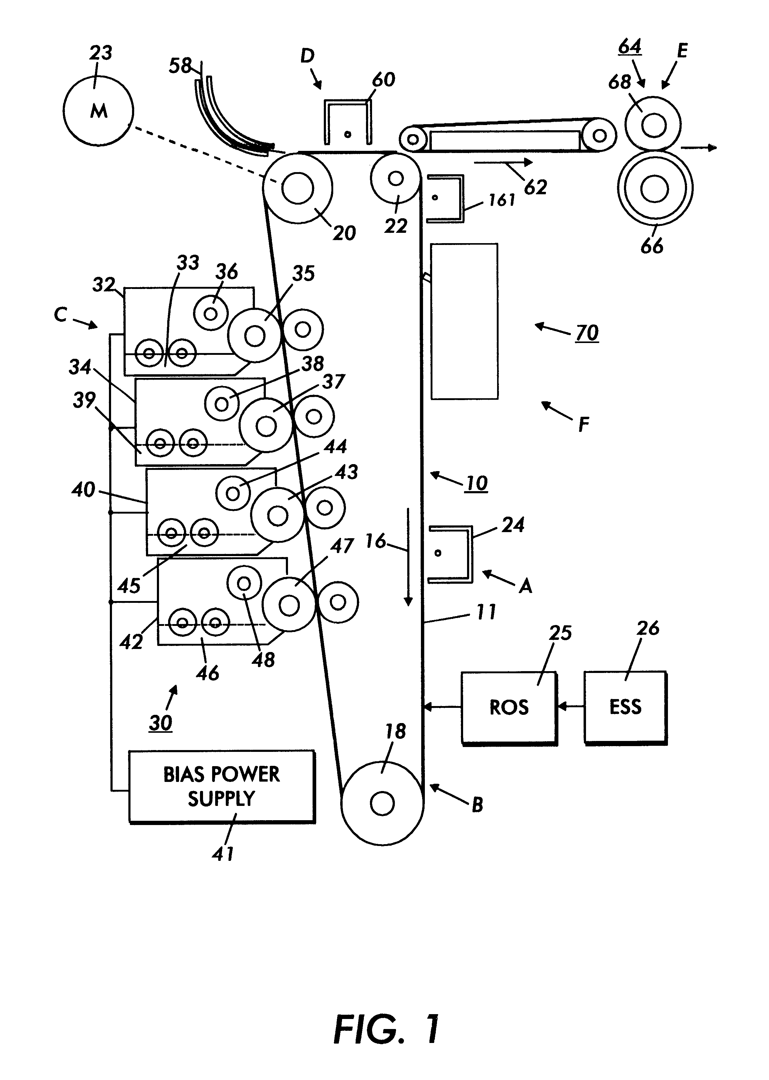
The foregoing generally describes a typical black and white electrostatographic printing machine. With the advent of multicolor electrophotography, it is desirable to use an architecture which comprises a plurality of image forming stations. One example of the plural image forming station architecture utilizes an image-on-image (IOI) system in which the photoreceptive member is recharged, reimaged and developed for each color separation, followed by a single transfer of all colors to paper. This greatly simplifies the transfer system, hence the system architecture, in comparison with a traditional system where each color is transferred to paper separately. As such, IOI machines can be single pass or multipass. In single pass IOI machines the charging, imaging, developing and recharging, reimaging and developing, etc followed by transfer to paper, are done in a single revolution of the photoreceptor. This requires multiple charging and imaging stations. In multipass IOI architectures, each color separation is formed with a single charging and imaging station but with different development stations, though still with a single transfer operation of all the colors. The single pass architecture offers a potential for much higher throughput.
Another approach to blooming problems is found in U.S. Pat. No. 5,519,815 relating an image processing method for reducing the amount of marking material required to print a colored image, and avoid problems common to the use of excessive amounts of ink. In a device for processing color images preparatory to printing, it provides a method of reducing marking material coverage in text and line art areas of secondary colors including the steps of: a) determining the locations of text and line art color pixels having excessive marking material coverage; b) upon determining the locations of color pixels having excessive marking material coverage, processing separation pixels to turn OFF a predetermined portion of the separation pixels corresponding to color pixels having excessive marking material coverage; and c) to prevent artifacts from occurring in the pixel reduction step, processing a given area of separation pixels in an order which tends to randomize the turn OFF effect.
U.S. Pat. No. 5,296,877 describes a multicolor printing process in which the shape and intensity of an imaging beam are changed when imaging a portion of a photoconductive element upon which toner has been deposited. Disclosed is a method of forming a multicolor image and apparatus capable of reducing the deviation between successive toner images of different colors and enhancing dot reproducibility. In the event of the second and successive sequences of steps included in a single multicolor image forming process, the intensity of a laser beam is controlled together with a beam diameter or an emission pulse width. This control is such that, when the laser beam scans part of the photoconductive element where a toner image was formed by the preceding sequence of steps, the laser beam forms a dot of substantially the same size in both the part where a toner image is present and part where a toner image is absent. This is performed in matching relation to the interception and scattering characteristics of the laser beam due to the toner image.
U.S. Pat. No. 5,252,995 describes a system in which the boundaries are enhanced between different color areas by varying the laser power. A multi-color, electrostatic, laser printing system employs a method for enhancing color representations at boundaries of pixels with different colors. The system employs a charged electrostatic surface that is selectively discharged by application of a modulated laser beam. The system performs the steps of: identifying a pixel of a first color that bounds a pixel of a second color, the first color being a secondary color; decreasing applied laser power to the electrostatic surface at the secondary color pixel site in the process of applying underprint and overprint toners to produce the secondary color; and inhibiting the decrease of applied laser power when applying the overprint toner if the second color pixel is a primary color that is the same as the color of the overprint toner of the secondary color pixel. A similar inhibition action occurs when an isolated primary color pixel or a thin pixel line is found so as to assure proper development.
U.S. Pat. No. 5,023,632 describes a method to vary the exposure between black and color toners by examining neighboring pixels around a target pixel. The logic applied here is to increase the exposure amount when all eight reference spots are in a non-exposure state, but use a reference exposure amount in any other situation. Disclosed is an electrophotographic color image forming method whereby black, yellow, magenta and cyan toner images are superimposed on a photoconductor to transfer to paper, exposure being changed between black and color in a method in which development of black is performed by a contact developing method, and development of color by a direct current electric field projection developing method. Also, in exposure for color, the exposure amount is adjusted between highlight and shadow areas. A full color image of high saturation with good balance between black and color components is reproduced by changing the exposure amount between black and color. It is also possible to obtain a color image with good reproducibility of highlight areas as well as shadow areas.
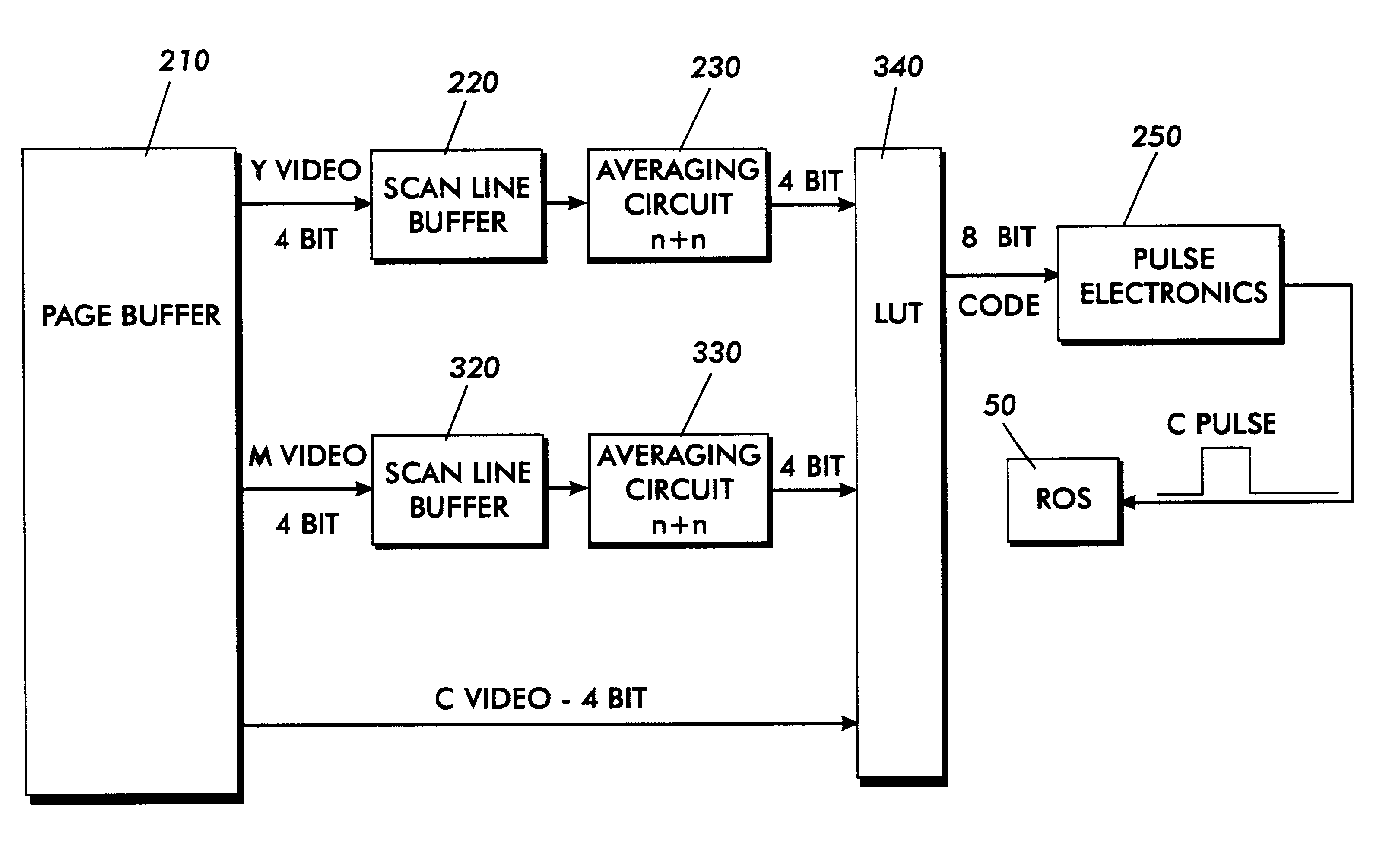
The present invention is directed to an apparatus and method for enabling full color saturation while avoiding undesirable image blooming in color systems.

Problems solved by technology

Blooming is a problem resulting from constraints in intensity and misalignment tolerances as found in many imaging scenarios and types.
However, color imaging systems such as video display monitors and print systems can also exhibit blooming problems in their output.
By "blooming" we are referring to shapes in an image which exceed their intended edges or boundaries and are thus larger than desired in a manner objectionable to the human eye.
This requirement creates a problem in the exposure step prior to this second toner development step.
This ultimately results in an insufficient mass of toner with attending color and saturation problems in the print.
However, such an increase, when applied to areas where there is no prior developed toner on the photoreceptor, means the exposure level is now too high, and this causes a "blooming" problem (i.e., line growth and narrow white space fill in).
Blooming as resulting from constraints in intensity and misalignment tolerances is a problem found in many imaging scenarios and types.
As may be noted from the discussion above, while there are many approaches to the problem of blooming, none of them satisfactorily address misregistration or misalignment in combination with intensity.
Furthermore, a two-level exposure control is too coarse an adjustment, as the compensation needed for imaging through a yellow toner layer is in general different from that required for imaging through a magenta toner layer, which is yet again different from that compensation required for imaging through the combination of both the yellow and magenta toner layers together.

Method used


Image

  • Method and apparatus for image compensation of blooming artifacts
  • Method and apparatus for image compensation of blooming artifacts
  • Method and apparatus for image compensation of blooming artifacts

Examples


Embodiment Construction

For a general understanding of a color electrostatographic printing or copying machine in which the present invention may be incorporated, reference is made to U.S. Pat. Nos. 4,599,285 and 4,679,929, whose contents are herein incorporated by reference, which describe the image on image (IOI) process having multi-pass development with single pass transfer. Although the image compensation for blooming method and apparatus of the present invention is particularly well adapted for use in a color electrostatographic printing or copying machine, it should become evident from the following discussion, that it is equally well suited for use in a wide variety of devices including video displays terminals and is not necessarily limited to the particular embodiments shown herein.

Referring now to the drawings, where the showings are for the purpose of describing a preferred embodiment of the invention and not for limiting same, the various processing stations employed in the reproduction machin...


PUM


Abstract

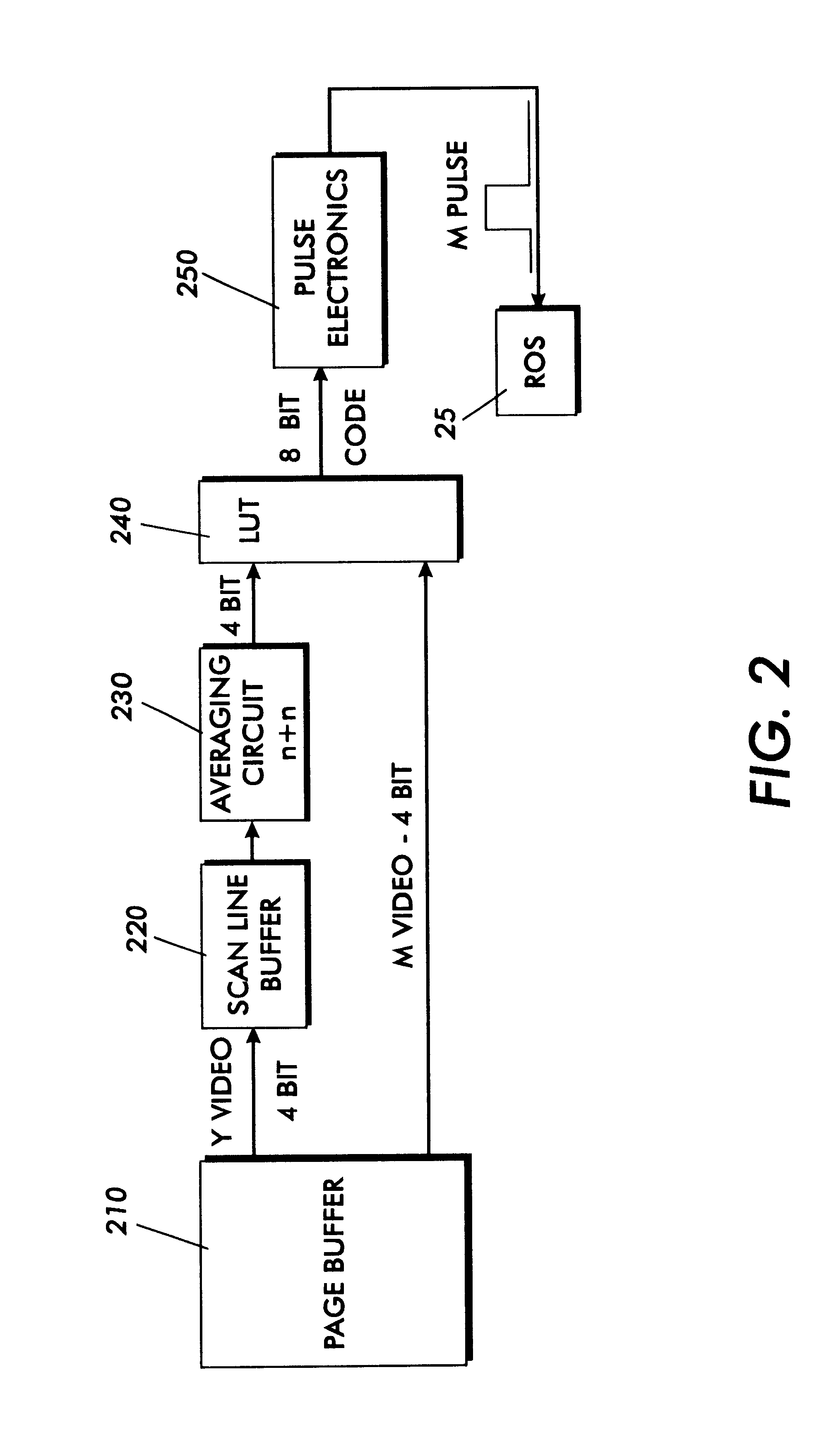
The present invention is a method and apparatus to minimize and prevent blooming problems in color image systems. Particular applicability is found where an image on image system is employed. The invention is inserted into the colorant driving signal path of the system. The invention places an averaging circuit in the path of one or more colorant driving signal streams. The averaging circuit produces an average value signal representative of a small area of its respective colorant. A modulator or other signal varying device responsive to the average value signal is placed in the path of yet another but separate colorant driving signal stream. In this manner the separate colorant driving signal is modulated or varied in response to the average neighboring value of a different color thus minimizing and preventing image blooming.

Description

BACKGROUND OF THE INVENTION AND MATERIAL DISCLOSURE STATEMENTThe present invention relates to a color imaging system wherein the average of one or more colors is used to modify the saturation of another color.Blooming is a problem resulting from constraints in intensity and misalignment tolerances as found in many imaging scenarios and types. Much of the art solving blooming problems is directed primarily toward video and CCD type cameras. However, color imaging systems such as video display monitors and print systems can also exhibit blooming problems in their output. By "blooming" we are referring to shapes in an image which exceed their intended edges or boundaries and are thus larger than desired in a manner objectionable to the human eye. Examples of blooming include, line growth and narrow white space fill in. Two important parameters affecting blooming in color systems are alignment, and saturation or intensity. The consequences of these two parameters are manifest in both co...

Claims


Application Information

Patent Timeline
Patent Type & Authority Patents(United States)
IPC IPC(8): G06K15/02H04N1/58H04N1/56
CPCG06K15/02H04N1/58G06K2215/0094
Inventor LIN, YING-WEILOJ, KATHERINE
Owner XEROX CORP
Why Eureka
Try Eureka