
All-pass optical filters

Inactive Publication Date: 2001-09-11
RPX CORP
View PDF8 Cites 139 Cited by
  • Summary
  • Abstract
  • Description
  • Claims
  • Application Information

AI Technical Summary

Problems solved by technology

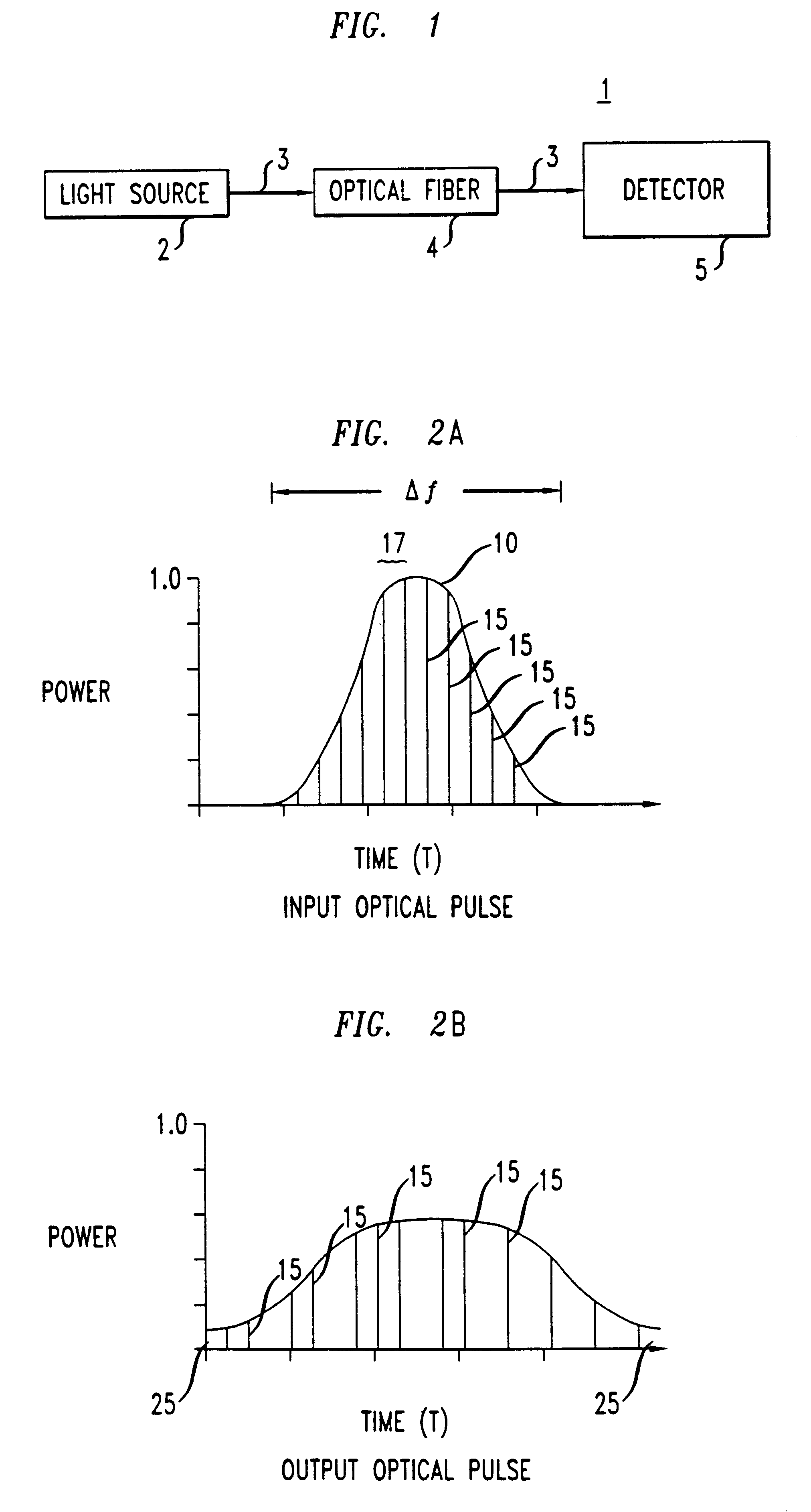
Broadening the optical pulse is undesirable because, depending on the time between optical pulses, the leading and trailing edges of the broadened pulse, denoted as 25, potentially interfere with the trailing edge of a previous optical pulse or the leading edge of a subsequent optical pulse, causing transmission errors.
However, dispersion compensating fibers are lossy (.about.5-10 dB).
Lossy fibers are undesirable because they potentially reduce the optical power of signals transmitted along their length.
Many chirped fiber Bragg gratings typically only compensate for quadratic dispersion, limiting their utility to systems with quadratic dispersion.
Additionally, chirped fiber Bragg gratings are long devices, making them expensive to integrate into optical communication systems.
The result is that a frequency-dependent loss, introduced by the filter, potentially reduces the useable pass-band width of the filter.
Additionally, the Takiguchi et al. dispersion equalizer is expensive and difficult to fabricate since a large number of symmetrical MZIs and asymmetrical MZIs are needed for dispersion compensation.
However, the single-stage cascaded fiber optic lattice filters of Moslehi et al. are lossy (.about.20 dB).
Since the Moslehi et al. devices are lossy, signal amplification is required for providing optical signals having adequate signal strengths for transmission along the optical fiber.
However, dispersion compensation using a single stage fiber ring structure affects the useable pass-band of the filter, reducing it.
However, the GTI arrangement only provides moderate dispersion compensation to the ultrashort laser pulses, limiting the ability for transmitting optical signals at high bit rates.
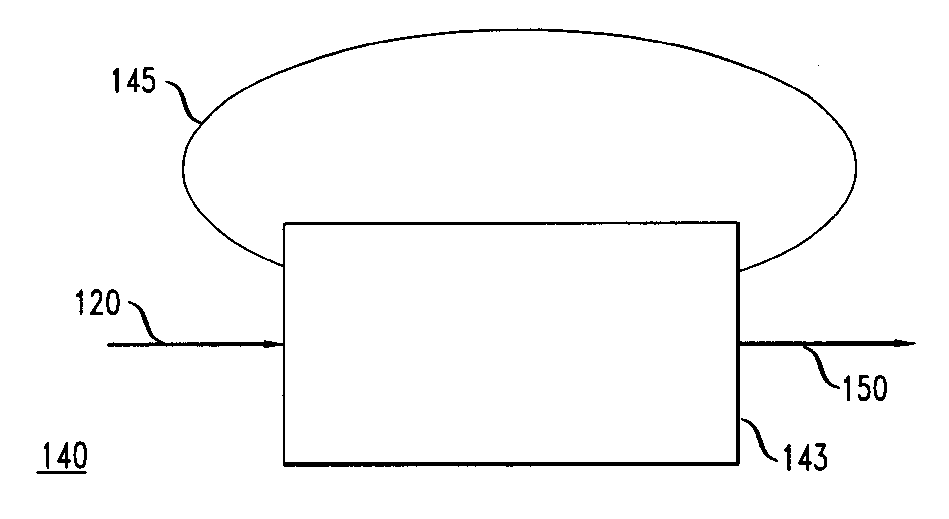
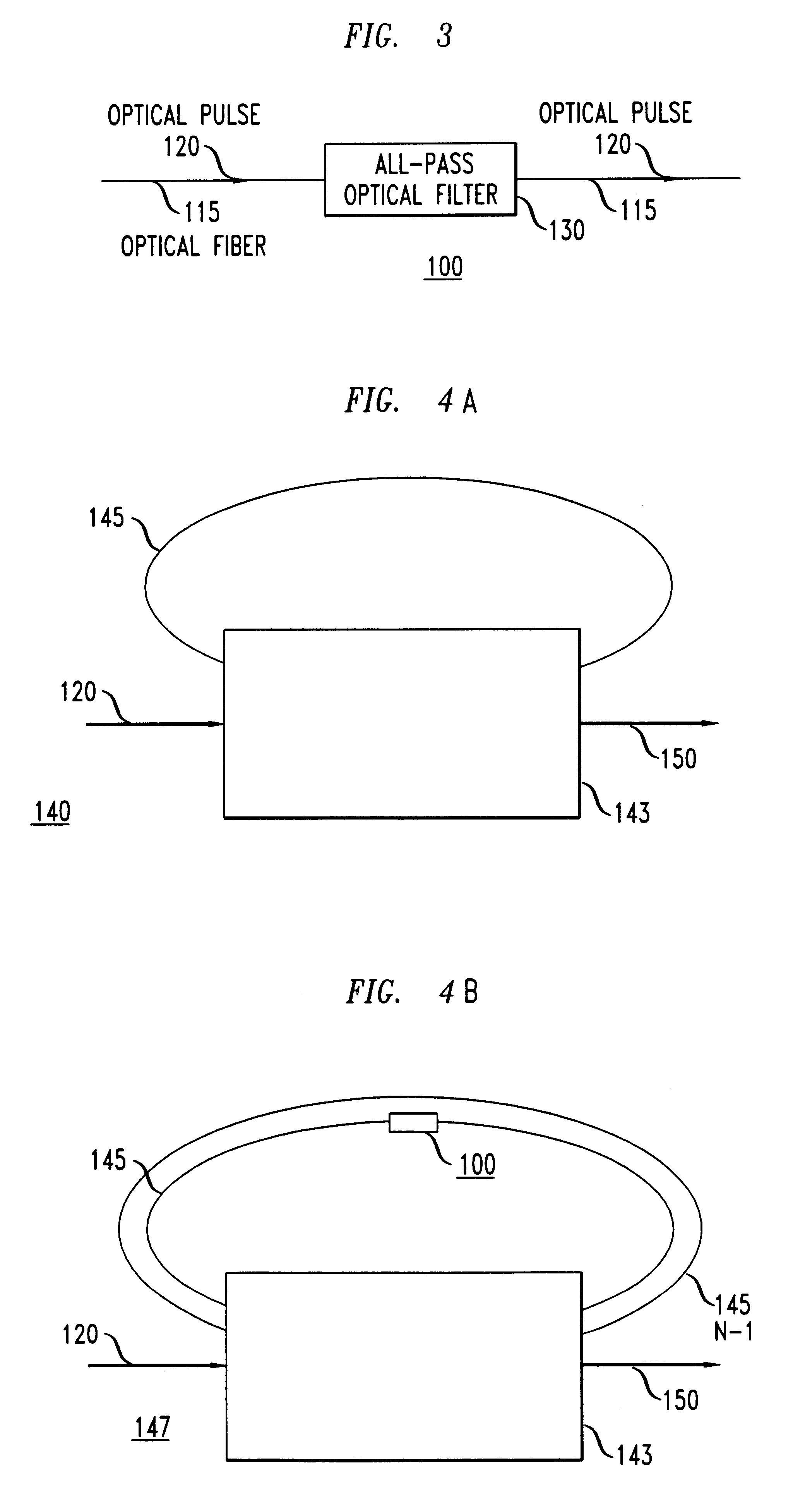
That is, the leading edge portions of the optical signal circulating in the feedback path interfere with the trailing edge portions of the optical signal being input thereto.
The problem is that even though the dispersion may be compensated perfectly at one wavelength, other wavelengths will have nonzero dispersion due to this dispersion slope.

Method used


Image

  • All-pass optical filters
  • All-pass optical filters
  • All-pass optical filters

Examples


example 2

All-pass optical filters are also usefull for delaying an optical pulse in time. A 4.sup.th order all-pass filter is chosen to approximate a delay time of 16 au (arbitrary units) over the normalized frequency range of 0.4 to 0.6. The filter parameters for a cascade structure using either rings (.kappa.,.phi.) or cavities (.rho.,.phi.+.pi.+.angle..rho.) are shown in TABLE 2.

The time delay for an all-pass optical filter with the parameters described above is shown in FIG. 11. The group delay applied to frequencies within the passband is essentially constant and much larger than the group delay applied to frequencies outside the passband.

example 3

An all-pass filter described below compensates for the dispersion slope of an optical fiber. The all-pass optical filter is designed to compensate the dispersion slope of 250 km of fiber over a 40 nm range. The difference in dispersion at 1525 nm and 1565 nm is designed to be 800 ps / nm, with the longest wavelength having the most negative dispersion. The FSR is chosen to be an integer multiple of the system channel spacing. For this example a value of 25 GHz is selected. The bandwidth over which the dispersion approximates a constant value is about 5 GHz. The all-pass optical filter parameters (phase, partial reflectors or couplers) are optimized at several wavelengths over the 40 nm range for the specific dispersion required at each wavelength. A set of filter parameters (one for each wavelength) are determined. The parameters are shown in TABLE 3 for a cavity structure. The phase values, .phi., of the all-pass optical filter were constrained to be constant to simplify fabrication ...


PUM


Abstract

An all-pass optical filter which reduces the dispersion of optical pulses transmitted therethrough is disclosed. The all-pass optical filter reduces the dispersion of optical pulses by applying a desired phase response to optical pulses transmitted therethrough. The all-pass optical filter also has a frequency independent amplitude response. The all-pass optical filter has a structure which includes at least one feedback path, a splitter / combiner, an input port, and an output port.

Description

The present invention relates generally to optical communication systems, and more particularly, to optical filters.DESCRIPTION OF THE RELATED ARTOptical communication systems typically include a variety of devices (e. g., light sources, photodetectors, switches, optical fibers, modulators, amplifiers, and filters). For example, in the optical communication system 1 shown in FIG. 1, a light source 2 generates an optical signal 3. The optical signal 3 comprises a series of light pulses. The light pulses are transmitted from the light source 2 to a detector 5. Typically, an optical fiber 4 transmits the light pulses from the light source 2 to the detector 5. The optical fiber 4 has amplifiers (not shown) and filters (not shown) positioned along its length. The amplifiers and filters propagate the light pulses along the length of the optical fiber 4 from the light source 2 to the detector 5.Optical communication systems are useful for transmitting optical signals over long distances at...

Claims


Application Information

Patent Timeline
IPC IPC(8): G02B6/122G02B6/34H04B10/18H04L25/03G02B6/28G02B6/00G02B6/12H04B10/2507
CPCB82Y20/00G02B6/1225G02B6/29343H04L25/03057G02B6/29356G02B6/29394H04B10/25133G02B6/2861G02B6/29353
Inventor KAZARINOV, RUDOLF FEODORLENZ, GADIMADSEN, CHRISTI KAYSCOTTI, RONALD EDWARD
Owner RPX CORP
Learn More