
Apparatus for and method of detecting a delay fault

Inactive Publication Date: 2001-09-18
ADVANTEST CORP
View PDF7 Cites 16 Cited by
  • Summary
  • Abstract
  • Description
  • Claims
  • Application Information

AI Technical Summary

Problems solved by technology

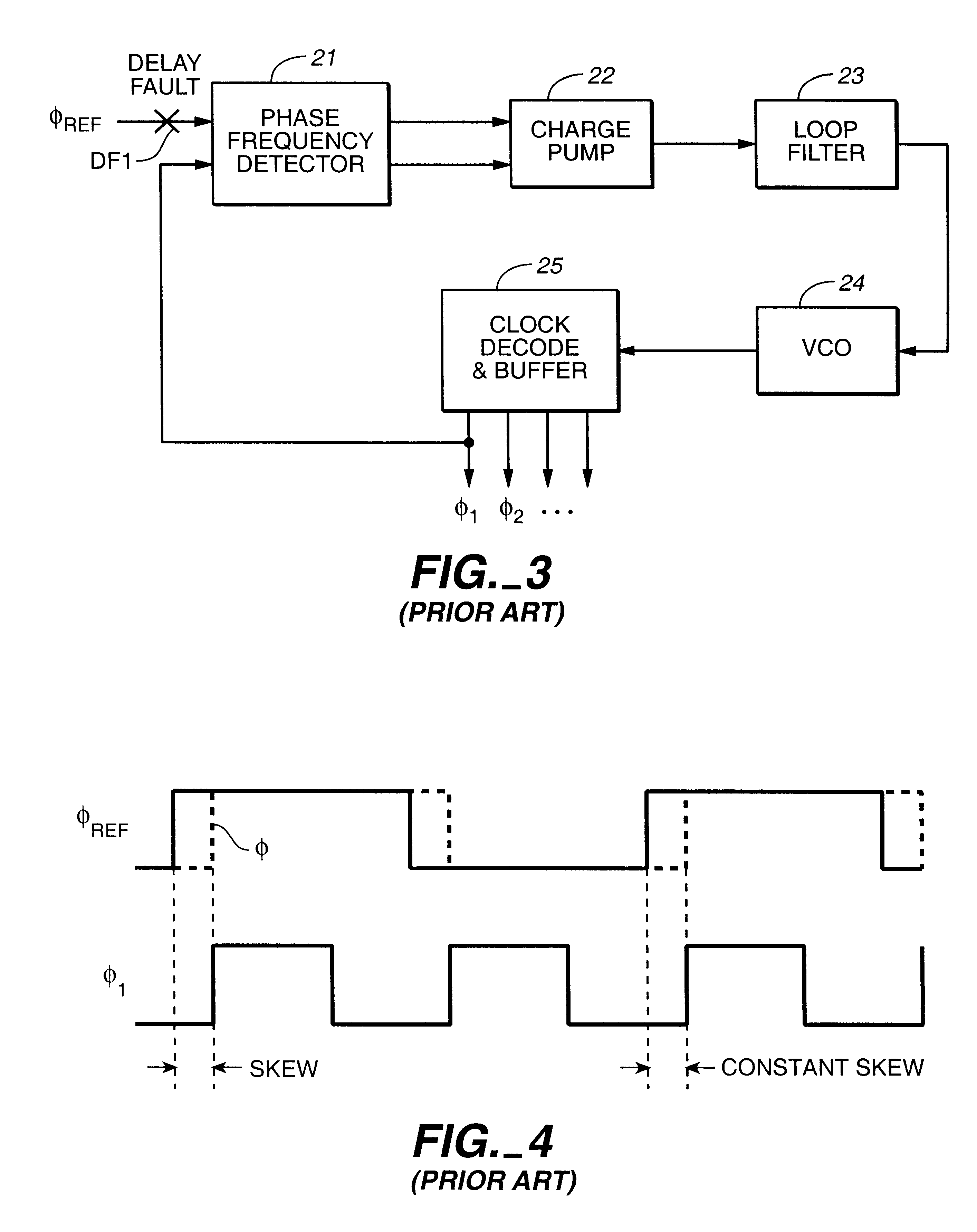
Accordingly, it is difficult to detect a delay fault at the reference clock input side even if internal blocks of the PLL circuit are tested.
Further, the delay of the analog signal causes a timing of an oscillation waveform of the VCO 24 to delay.
In this manner, since a PLL circuit is a feedback system, a transient skew occurs.
A timing at which a transient skew occurs is limited, and hence it is difficult to detect the transient skew by a test.
This clock skew is not compensated in the PLL circuit.
As a cause of this type of fault, there can be considered a defect that a short circuit has been formed between the output of the inverter and a power supply voltage V.sub.DD or a physical defect that a drain of an nMOS (n-channel metal-oxide semiconductor) has been opened.
If a delay time occurring when a signal propagates through a gate exceeds the worst value, it is said that this gate has a gate delay fault present therein.
Similarly, if a delay time occurring when a signal propagates on a signal path exceeds the worst value, it is said that the signal path has a path delay fault present therein.
It is very difficult to generate test patterns for a delay fault testing.
As VLSI circuits are developing more and more in their density and scale, it is more difficult to synchronize all of the edges of clocks generated within a chip with the edge of the reference clock and to distribute the clock with the minimum skew.
However, the conventional delay fault testing method is not suitable for efficiently testing clock-distribution networks.
That is, this results in a self-contradiction.

Method used


Image

  • Apparatus for and method of detecting a delay fault
  • Apparatus for and method of detecting a delay fault
  • Apparatus for and method of detecting a delay fault

Examples


Embodiment Construction

Now, the present invention will be described regarding its preferred embodiments in detail with reference to FIGS. 13 to 32. In this section, a principle of the proposed delay test will be described. The subject delay fault in this section does not include the delay fault present at the reference clock input end of the phase-frequency detector which has been made clear in the section 4.1.2.

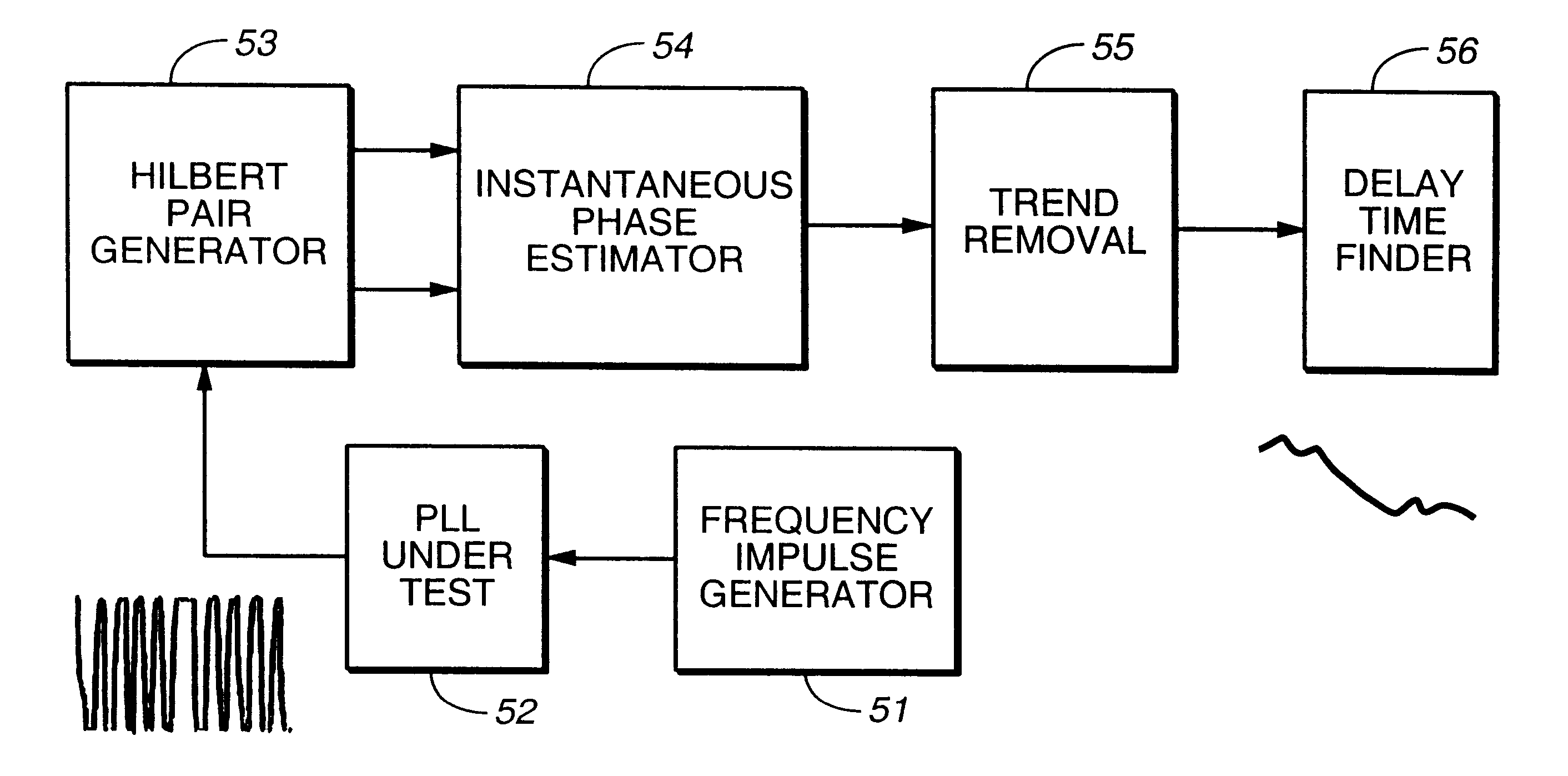
First, the principle of the method of detecting a delay fault according to the present invention will be discussed. An output of a phase-frequency detector in a PLL circuit provides a VCO with a phase difference (differential of phase) from the reference clock at each time point. The VCO changes its oscillation frequency to track the frequency of the reference clock. Incidentally, an instantaneous frequency .DELTA.f is given by differentiating an instantaneous phase waveform .theta.(t) with respect to time. ##EQU1##

When .DELTA.f is constant, it is seen from the equation (4.1.1) that an instantaneo...


PUM


Abstract

There is provided a method of and an apparatus for detecting delay faults in phase-locked loop circuits. A frequency impulse is applied to a phase-locked loop circuit under test as the reference clock, and a waveform of a signal outputted from the phase-locked loop circuit under test is transformed to an analytic signal to estimate an instantaneous phase of the analytic signal. A linear phase is estimated from the estimated instantaneous phase, and the estimated linear phase is removed from the estimated instantaneous phase to obtain a fluctuation term of the instantaneous phase. A delay time is measured from this fluctuation term of the instantaneous phase, and further, a delay fault is detected by comparing a time duration during which the phase-locked loop circuit remains in a state of oscillating a certain frequency with a time duration during which a fault-free phase-locked loop circuit remains in a state of oscillating that certain frequency.

Description

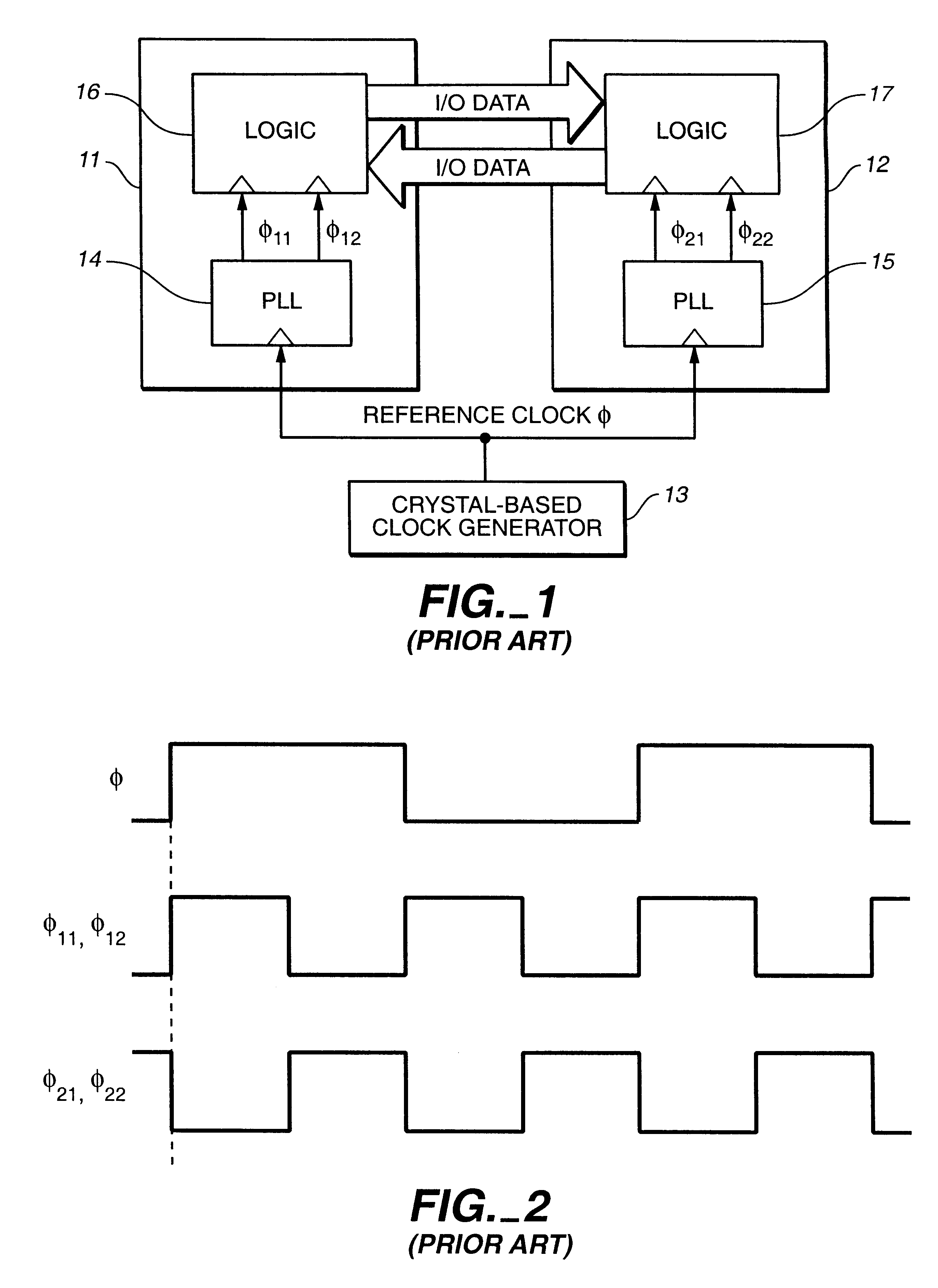
1. Field of the InventionThe present invention relates to an apparatus for and a method of detecting a delay fault in a phase-locked loop circuit, and more particularly, relates to a delay fault detecting apparatus and a delay fault detecting method which are suitable for detecting delay faults in phase-locked loop (hereinafter referred to as PLL) circuits formed on VLSI (very large scale integrated circuit) chips respectively.2. Description of the Related ArtA synchronous system performs a cooperative operation by sharing a timing of a clock edge with one another. The more the timing of the shared edge is controlled at high accuracy, the more the synchronous system can operate at a high rate. FIG. 1 shows an example of the synchronous system. This system has such a configuration that a plurality of (in this example, two) VLSI chips 11 and 12 are placed on a single board (not shown). A reference clock .phi. is supplied to each of the VLSI chips 11 and 12 from a high precision oscill...

Claims


Application Information

Patent Timeline
IPC IPC(8): G01R31/28G01R31/30G01R25/00
CPCG01R31/3016G01R31/2839G01R25/00
Inventor SOMA, MANIYAMAGUCHI, TAKAHIROISHIDA, MASAHIRO
Owner ADVANTEST CORP
Learn More