Control for a fluid pressure supply system, particularly for high pressure in a fuel injection system

a fluid pressure supply and control technology, applied in the direction of electric control, positive displacement liquid engine, pump parameter, etc., can solve the problems of insufficient response behavior and too slow control speed in certain areas of application, lack of dynamics, and the high pressure area, i. e. the common rail, cannot be relieved

Inactive Publication Date: 2001-09-25
CONTINENTAL AUTOMOTIVE GMBH
View PDF16 Cites 58 Cited by
  • Summary
  • Abstract
  • Description
  • Claims
  • Application Information

AI Technical Summary

Problems solved by technology

Comparatively elaborate electronic sensor devices and corresponding electronic devices are therefore connected with the known suction throttle control which--as has been found--still has an inadequate response behavior and too slow a control speed for certain areas of application.
In the known case this lack of dynamics appears in particular when it is necessary to relieve the pressure in the common rail extremely rapidly.
Although the suction throttle valve can be rapidly closed in this case, the high-pressure area, i. e. the common rail, can only be relieved as the result of amounts of leakage or remaining injection amounts.

Method used


Image

  • Control for a fluid pressure supply system, particularly for high pressure in a fuel injection system
  • Control for a fluid pressure supply system, particularly for high pressure in a fuel injection system
  • Control for a fluid pressure supply system, particularly for high pressure in a fuel injection system

Examples


Embodiment Construction

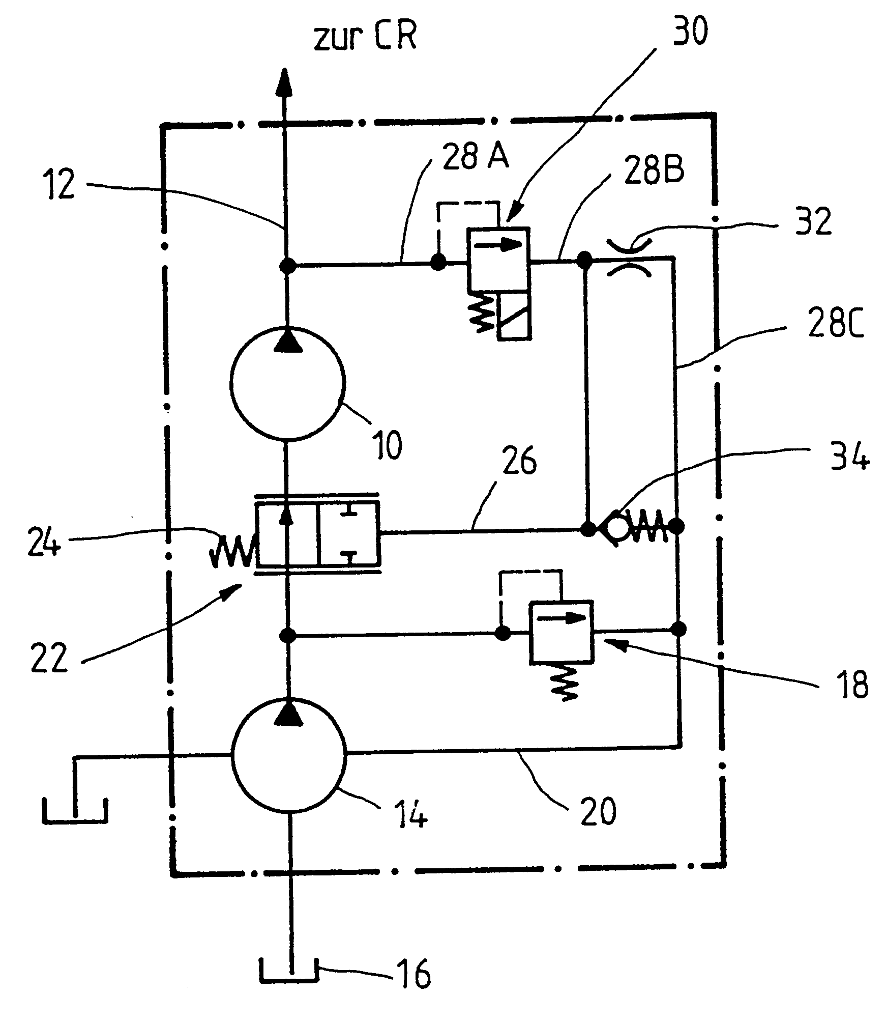
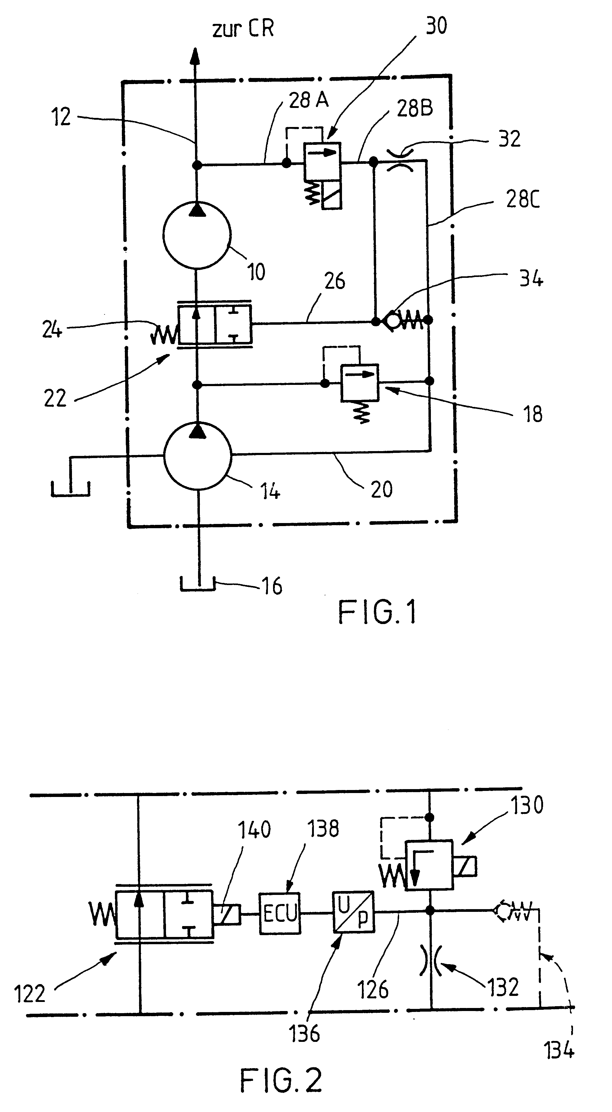
A high-pressure pump in FIG. 1 is identified by the reference numeral 10, which for example is designed as a radial piston pump and is able to build up extremely high pressures in a high-pressure line 12 leading to the so-called "common rail" of a fuel injection system. The high-pressure pump 10 is designed similar to a radial jet pump, i.e. it is able to provide a changing conveying output with an unchanged stroke and as a function of the pressure fluid supply. The high-pressure pump is supplied by a pre-conveying pump 14, i.e. a low-pressure pump, which aspirates pressure fluid, i.e. fuel, from a tank 16. The pre-conveying pump 14 is protected by means of a pressure control valve (5 bar valve) 18. The corresponding return line leading via the pre-conveying pump 14 to the tank is identified by 20. In order to control the pressure in the common rail, to which individual consumers, not shown in detail, in particular injection nozzles of the internal combustion engine, are connected, ...


PUM


Abstract

A control for a pressure fluid supply system is described, in particular for the high pressure in a fuel injection system, for example for an internal combustion Diesel engine, by means of which the pressure in a common high-pressure line supplied by a high-pressure pump, i.e. in the common rail, to which individual consumers are connected, is controlled in accordance with the instantaneous pressure fluid requirements. For adapting the pressure in the common high-pressure line to the pressure fluid requirements of the consumers, i.e. the injection nozzles, a device for limiting the amounts of fluids conveyed is associated with the high-pressure pump, which has at least on adjusting element which can be changed by means of an adjusting signal representing the instantaneous pressure fluid supply situation in the common rail. To avoid an elaborate pressure sensor device in the common rail and for the simultaneous improvement of the reaction behavior of the control, in particular when reducing the high pressure in the common rail, the adjusting signal is derived from the amount of fluid throughput in the delivery line of a pressure control valve connected to the common rail. The pre-conveying pressure or the pre-conveying amount available to the high-pressure pump is affected by means of this adjusting signal in the sense of a regulation of the pressure in the common rail.

Description

The invention relates to a control for a pressure fluid supply system, in particular for the high pressure in a fuel injection system, for example for an internal combustion Diesel engine, in accordance with the preamble of claim 1.PRIOR ARTA control of this type has become known, for example, from the document EP 0 299 337 A2. A suction throttle located in the suction line of the high-pressure pump is employed here as the device limiting the amount of fluid conveyed, which is set in accordance with the pressure fluid requirement of the consumers in such a way that the high-pressure pump only conveys the actually required pressure fluid amounts into the common high-pressure line, i.e. the common rail. In this known case this is referred to as suction pressure control, which operates as follows:A pressure sensor is provided in the common high-pressure line, i.e. the common rail, whose pressure signal is provided to a control unit which, as a rule, operates electronically, and is comp...

Claims


Application Information

Patent Timeline
Patent Type & Authority Patents(United States)
IPC IPC(8): F02M63/00F02M63/02F02M59/36F02M59/20F02D41/38F04B49/08
CPCF02D41/38F02M59/36F02M63/0225F04B49/08F04B2205/172F04B2201/0807F04B2205/10F04B2205/171
Inventor ARNOLD, BERNHARDEISENBACHER, EGONPAWELLEK, FRANZ
Owner CONTINENTAL AUTOMOTIVE GMBH
Why Eureka
Try Eureka