
Method and flow system for spectrometry and a cuvette for the flow system

a flow system and flow system technology, applied in the direction of material testing goods, testing food, instruments, etc., can solve the problems of dissolved air, measurement results that will obviously not show the correct analysis of milk products themselves, thin milk layers tend to adhere to the ir-windows of the cuvette, etc., to achieve optimal production

Inactive Publication Date: 2001-10-02
FOSS ELECTRIC
View PDF21 Cites 60 Cited by
  • Summary
  • Abstract
  • Description
  • Claims
  • Application Information

AI Technical Summary

Benefits of technology

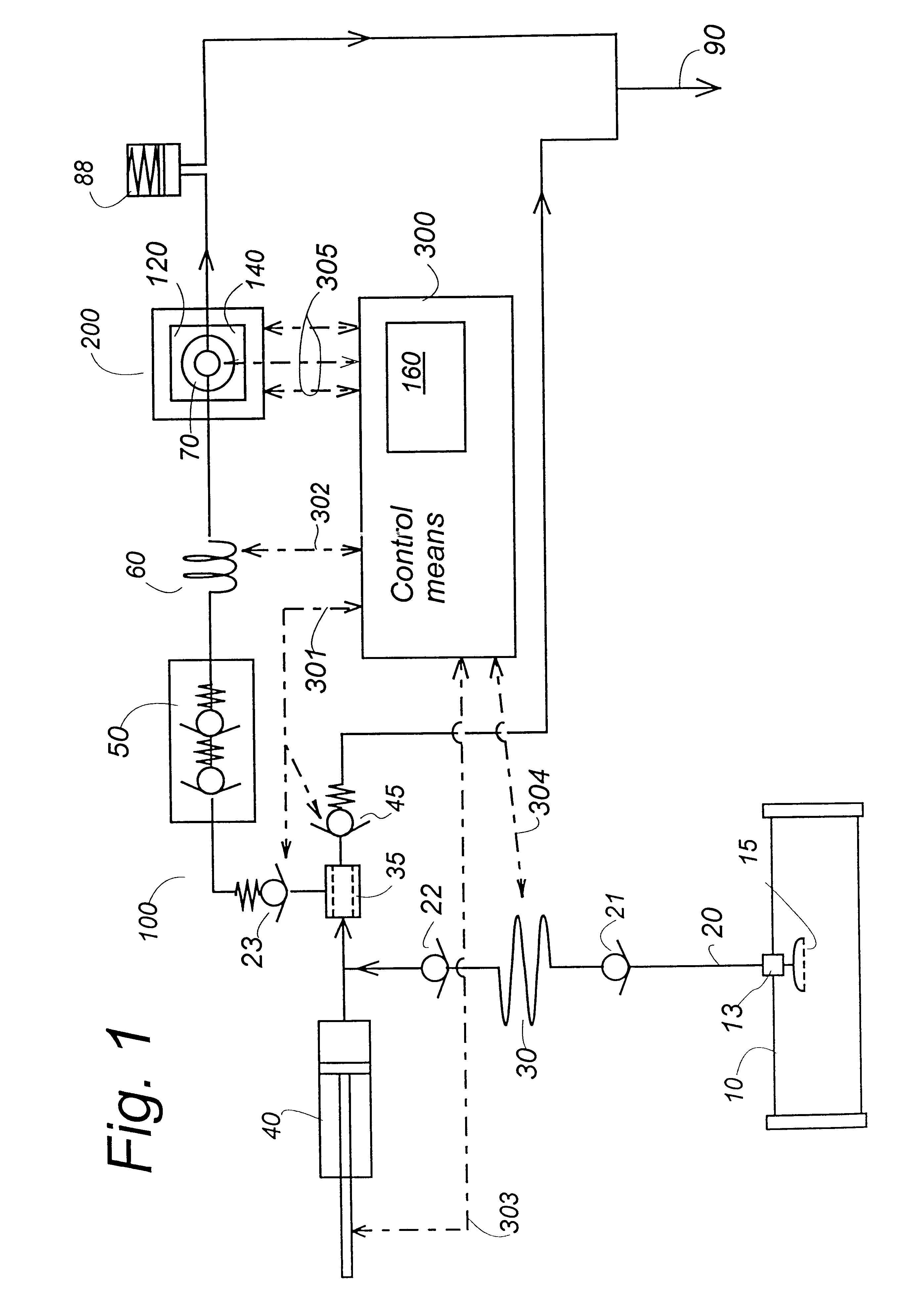
The measurement takes place at normal process line pressure or even higher. Therefore, dissolved gases will not be released and accordingly, no air bubbles are produced. The measuring system is chemical resistant to all substances which stainless steel is resistant to. (This feature is an advantage during a regular cleaning of the food product processing system). The diamond windows ensure that the mechanical dimensions of the optical system are not subject to changes due to mechanical wear. The measuring system can operate in a process environment for a long time without any need for attended operators to perform zero adjustment, re-calibration, separate cleaning or other kind of maintenance operation on the flow system and IR measurement equipment. The measurement is an on-line measurement, always available to maintain an optimal production. Regularly, during normal operation, the flow system is "cleaned" by the samples themselves. Preferably, in a preferred embodiment, the normal process line cleaning procedure includes the measuring branch, i.e. the above mentioned flow system. Further, in the preferred embodiments, no "foreign" substances are introduced, i.e. no special cleaning or calibration agents are needed besides the cleaning and rinsing agents generally used in dairies. Therefore, a possible option comprises the return of the sample to the process line after the measurement.

Problems solved by technology

Testing milk in-line in a process plant in a dairy presents several problems.
One problem is due to dissolved air, which is normally present in the raw milk.
If air bubbles are released and enter the measuring cuvette, the measurement result will obviously not show a correct analysis of the milk product itself.
A further problem is that milk includes several components and specifically the fat globules can give reason to failures.
A further problem is that thin layers of milk tend to adhere to the IR-windows of the cuvette.
The measurements may be seriously deteriorated due to such milk coatings.
In fact the cuvette is highly exposed to wear as the liquid product and rinsing and cleaning solutions pass through the cuvette under high pressure and flow rates.
It has therefore until now not been possible to perform the desired testing procedures on milk in an in-line system.
Other window materials might break or move causing the cuvette to widen and to thereby causing the IR transmission loss through the cuvette to raise, thereby influencing the measurement result.

Method used


Image

  • Method and flow system for spectrometry and a cuvette for the flow system
  • Method and flow system for spectrometry and a cuvette for the flow system
  • Method and flow system for spectrometry and a cuvette for the flow system

Examples


second embodiment

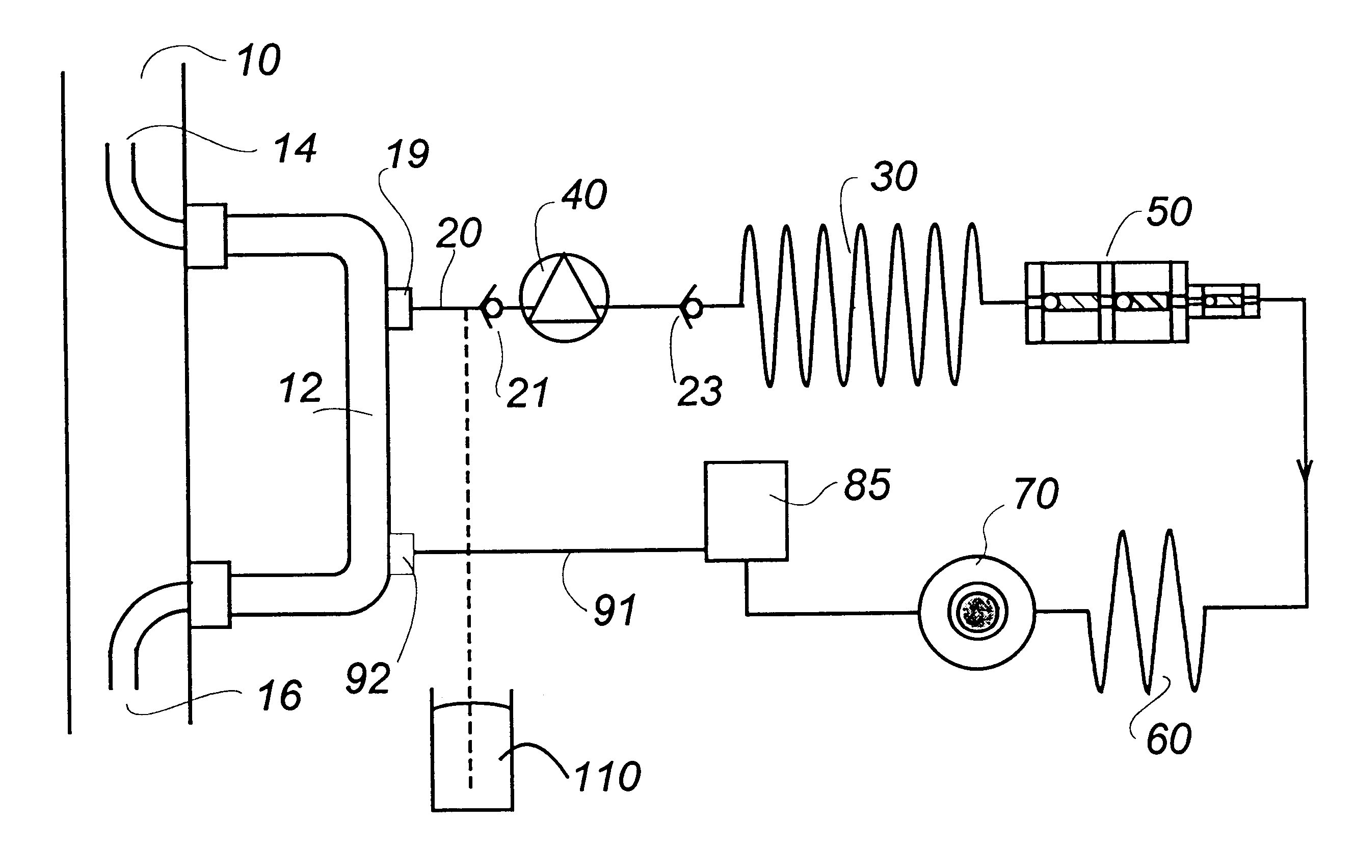
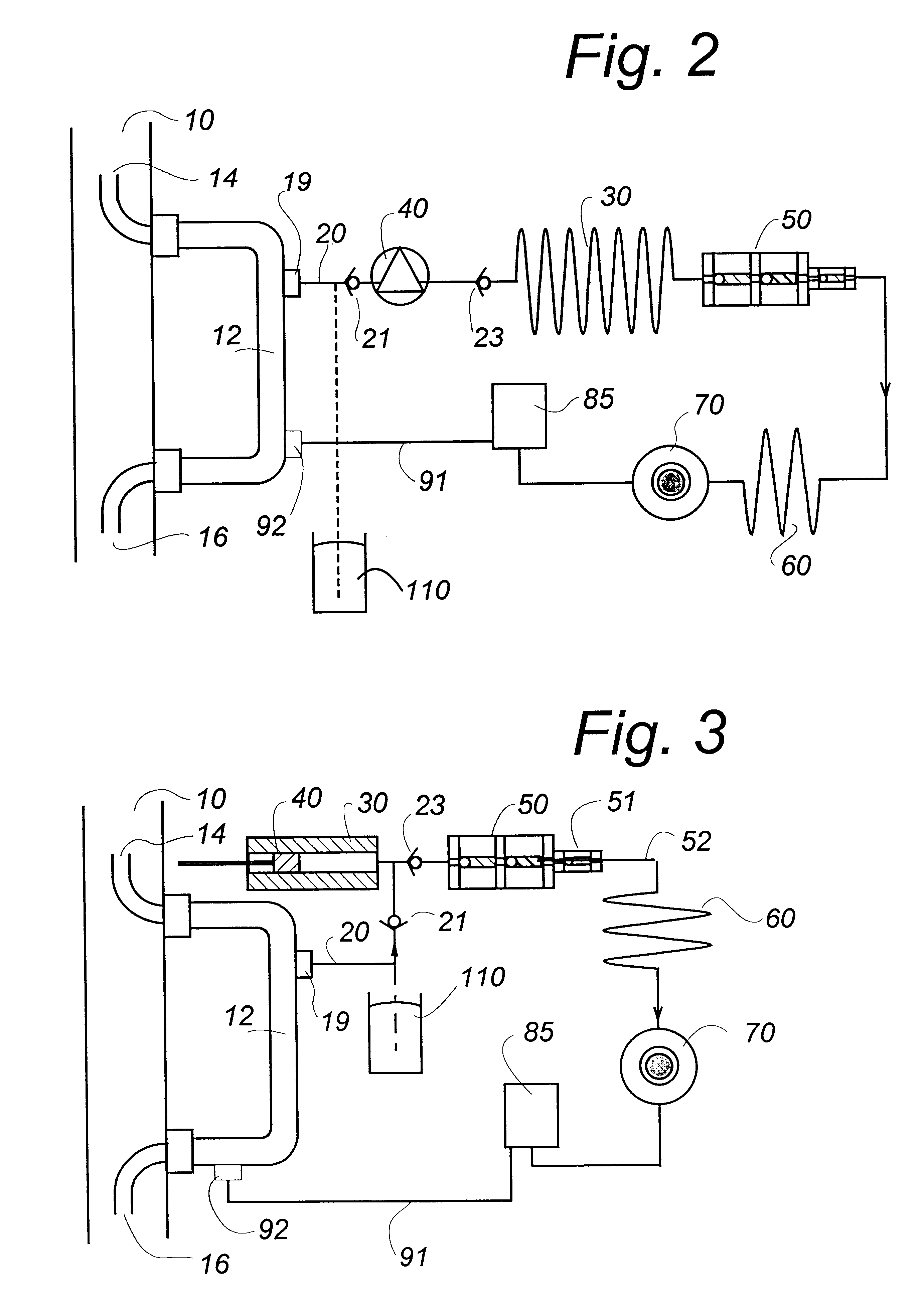
In a second embodiment shown in FIG. 2 the flow system comprises: a fast-loop, i.e. an U-formed tube 12 having an inlet 14 and an outlet 16 arranged inside a process conduit 10 which is part of a process plant such as a dairy, which is not shown in the drawings. The is fast-loop tube 12 is small compared to the process conduit 10. Typically the inner diameter of the fast loop is about 10 mm in a process conduit 10 having an inner diameter of about 70 mm. The drawing does not show the true dimensions.

The inlet 14 opens towards the direction of the process flow in the conduit 10, in such a way that a fraction of the process flow is diverted through the fast-loop. At the outlet 16 the process flow will generate suction, forcing the diverted flow to return into the process conduit 10.

A sample intake is provided by a tiny flexible tube 20, having an inlet opening with filter communicating with the fast-loop through a detachable connection e.g. so-called mini clamps 19 comprising two flan...

third embodiment

By the embodiment shown in FIG.3 the pump 40 is a single stroke pump surrounded by heating means, e.g. a coil. The method is carried out as follows: In a first step of about two sec's a sample is sucked into the pump cylinder by one suction stroke of the piston. Then in a second step the sample is heated inside the pump cylinder for about 25 secs. In a third preferably short step of about 0.5-1.0 sec. duration the piston stroke is reversed, pushing the new sample through the homogenizer and partly through the cuvette and the back pressure valve. Thereby the old sample is flushed away either into a waste outlet 90 or returned into the fast loop and the process conduit If the third step is performed in 0.5 sec. the flushing rate through the cuvette will be about 10-30 m / s with a displaced milk volume of about 1.5 ml. This flushing rate will ensure a thorough cleaning of the cuvette windows between each measurement. The advantage of the third embodiment is that the suction stroke may b...


PUM


Abstract

The present invention relates to an on-line method and a flow system as well as a cuvette for carrying out IR spectrometry for analysis of liquid food products, possibly containing dissolved gases, in a process line in a liquid food product processing plant, especially a dairy processing milk and milk products. A liquid sample is extracted from the process line to a measuring branch, the sample is thermostated and passed to a measurement cuvette. The IR-absorbance spectrum is measured, e.g. in the MID-IR or NIR-range. In order to obtain an on-line monitoring of the process line the liquid food sample is extracted directly from the process line into the measurement branch, in which the pressure is maintaining at least as high as in the adjacent process line. The high pressure ensures that dissolved air will stay dissolved in the liquid food. Before each new sample the measurement branch and cuvette are flushed by high flow rates with a part of the new sample to clean the cuvette. The measurement cuvette has strong windows, preferably diamond windows to stand a high pressure and high flow rates. The on-line system is arranged to carry out eg. 120 measurements per hour.

Description

The present invention relates to a method and a flow system for carrying out spectrometry for analysis of a liquid food product, possibly containing dissolved gases, in a process line in a liquid food product processing plant, especially milk and milk products in a dairy, and comprising the following steps: 1) providing a liquid food sample from the process line to a measuring branch, 2) thermostating the liquid food sample, 3) passing the thermostated liquid food sample to a sample cuvette, 4) measuring at least part of the absorbance spectrum of the liquid food sample in the sample cuvette. The invention also relates to a measurement cuvette for the flow system. The present invention is specifically intended for IR-measurements, e.g. MID-IR and / or NIR-measurements for a determination of the quantities of specified components in the liquid food product.A presently used method includes providing a milk sample from the process plant in an open sample container or cup from which disso...

Claims


Application Information

Patent Timeline
IPC IPC(8): G01N21/03G01N21/05G01N21/35G01N21/31G01N33/04G01N21/11G01N21/3577G01N21/359G01N35/08
CPCG01N21/05G01N21/359G01N21/3577G01N21/0303G01N33/04G01N2021/0378G01N2021/0346
Inventor FRANDSEN, ANDREAS SK.AE BUTTED.RLUNDPEDERSEN, S.O SLASHED.REN CHRISTIANRIDDER, CARSTENTHOMSEN, HENRIK
Owner FOSS ELECTRIC
Learn More