
Process for CO2/natural gas separation

a natural gas and co2 technology, applied in the field of co2/natural gas separation, can solve the problems of reducing the separation performance of polymeric membranes, major problem of being vulnerable to fouling, and reducing selectivity

Inactive Publication Date: 2001-10-09
THE UNIV OF TEXAS SYST
View PDF10 Cites 55 Cited by
  • Summary
  • Abstract
  • Description
  • Claims
  • Application Information

AI Technical Summary

Problems solved by technology

It is known that impurities including heavy, condensable hydrocarbons, i.e., C.sub.6 and greater, substantially reduce separation performance of polymeric membranes.
However, like polymeric membranes, they also have the major problem of being vulnerable to fouling due to impurities in various hydrocarbon compounds.
For example, certain hydrocarbon impurities cause selective fouling of the carbon membrane resulting in reduced selectivity.
Even small amounts of such hydrocarbons can significantly impair the performance of the membrane.
These measures may involve the use of large, expensive equipment and are often not successful.
Another deficiency of known carbon membranes is an inability to perform well with high pressure feeds.
Reducing the pressure to satisfy membrane pressure limits is economically disadvantageous.
If pressure is reduced, expensive compressors may be required to increase the pressure of the stream for passage through an export pipeline.
None of these patents teaches CO.sub.2 / CH.sub.4 separation, especially at high pressure or in the presence of impurities.
The prior art references do not teach a process for CO.sub.2 --natural gas separation using a carbon membrane at high pressures and in the presence of impurities.

Method used


Image

  • Process for CO2/natural gas separation
  • Process for CO2/natural gas separation
  • Process for CO2/natural gas separation

Examples


example 1

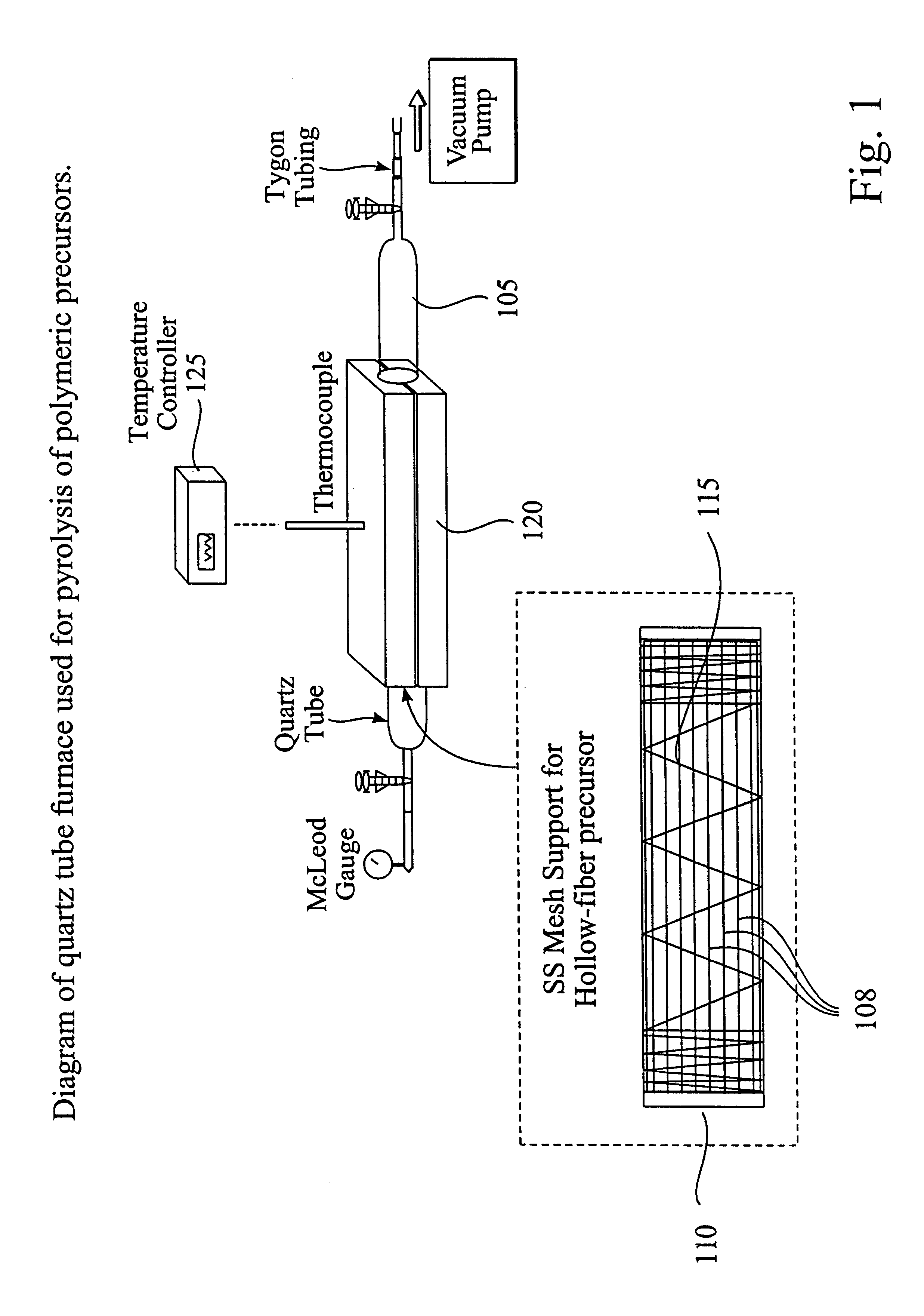
CMS hollow fiber membranes were prepared as described in Sections A and B. Elemental analysis (electron spectroscopy for chemical analysis) indicated the presence of 95% atomic carbon and 5% atomic oxygen. Scanning electron micrographs (SEM) indicated an outer diameter of 150 to 170 .mu.m and an inner diameter of 90 to 110 .mu.m. The approximate mass loss is 30 to 35%. The approximate fiber length shrinkage was 10 to 25%.

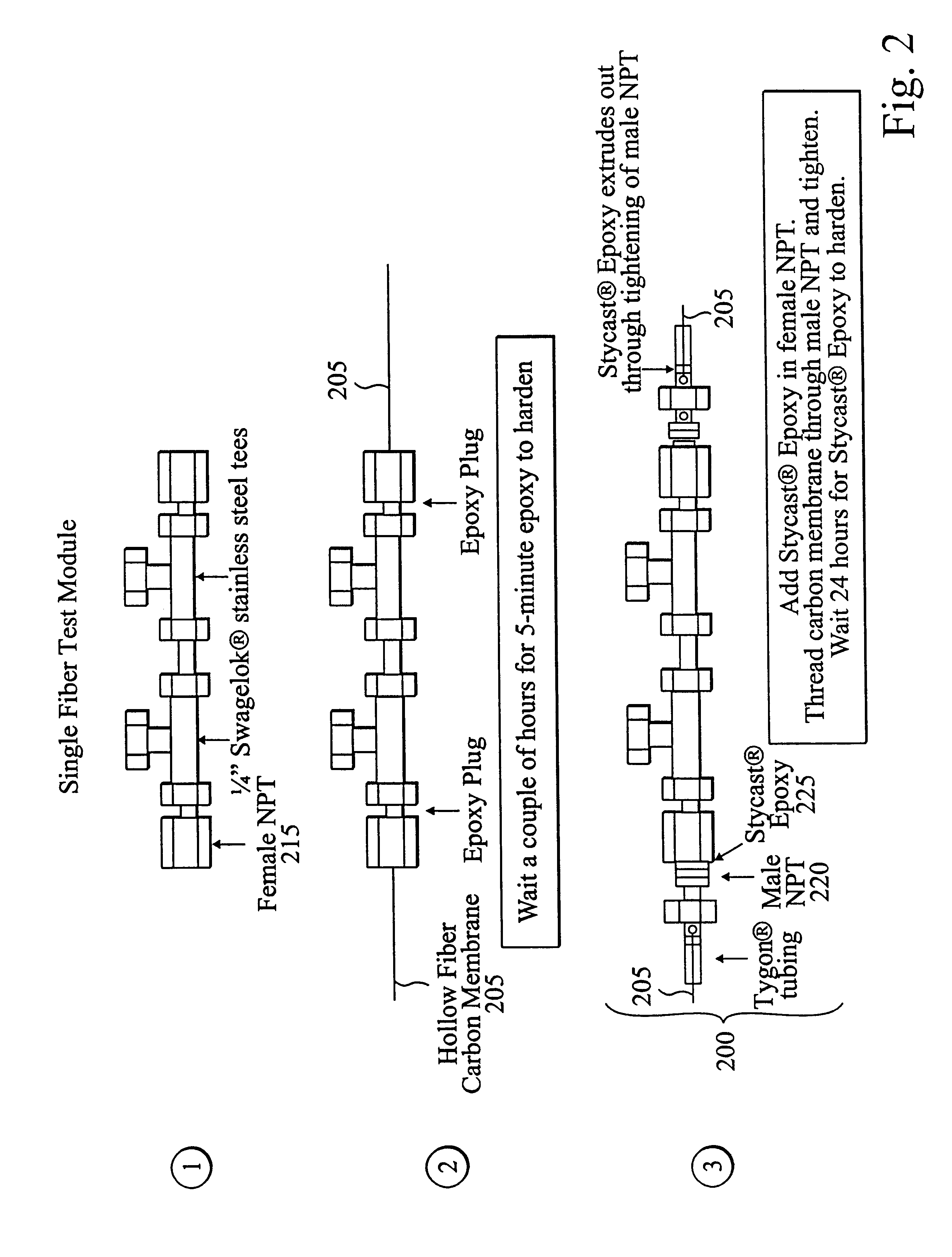
Permeation tests were performed according to Section C above with mixed feed gas of 10% CO.sub.2 and 90% CH.sub.4 at three different temperatures (24.degree. C., 35.degree. C., 50.degree. C.) and feed pressures up to 1000 psia. Results are shown in Table 1 below for the 200 to 1000 psia feed pressure range. Permeance is defined as the pressure-normalized flux of a given compound. The table includes CO.sub.2 permeance (P.sub.CO2 / l) and the permeance ratio (P.sub.CO2 / P.sub.CH4). The effective thickness, l, in the permeance is the same for both compounds. Both P.sub....

example 2

CMS hollow fibers fabricated from Example 1 were subjected to experiments with toluene exposure for the 200 to 1000 psia feed pressure range. Permeation tests were performed according to Section C with mixed feed gas of 10% CO.sub.2 and 90% CH.sub.4 for two cases: (1) Case 1 containing a third component of 70.4 ppm toluene and (2) Case 2 containing a third component of 295 ppm toluene. Two temperatures were evaluated for each case: 35.degree. C. and 50.degree. C. Results for Case 1 over the 200 to 1000 psia feed pressure range are shown in Table 2. Similar results were obtained for Case 2. Comparisons with the pre-exposure results for the same module indicate that CO.sub.2 permeance (P.sub.CO2 / l) was reduced by approximately 15 to 20% for either toluene case, while the permeance ratio (P.sub.CO2 / P.sub.CH4) remained approximately constant.

example 3

CMS hollow fibers fabricated from Example 1 were subjected to experiments with n-heptane exposure for the 200 to 1000 psia feed pressure range. Permeation tests were performed according to Section C with mixed feed gas of 10% CO.sub.2 and 90% CH.sub.4 for two cases: (1) Case 1 containing a third component of 100 ppm n-heptane and (2) Case 2 containing a third component of 302 ppm n-heptane. Two temperatures were evaluated for each case: 35.degree. C. and 50.degree. C. Results for Case 2 over the 200 to 1000 psia feed pressure range are shown in Table 3. Similar results were obtained for Case 1. Comparisons with the virgin 10% CO.sub.2 / 90% CH.sub.4 results for the same module indicate that CO.sub.2 permeance (P.sub.CO2 / l) was reduced by approximately 10 to 15% for either n-heptane case, while the permeance ratio (P.sub.CO2 / P.sub.CH4) remained approximately constant.


PUM

PropertyMeasurementUnit
Percent by massaaaaaaaaaa
Temperatureaaaaaaaaaa

Abstract

The invention includes a process for separating CO2 from natural gas including: contacting a mixture of CO2 and natural gas with a first side of a carbon membrane in a manner to cause a portion of the mixture to pass through the carbon membrane to a permeate side. The resulting mixture on the permeate side becomes enriched in CO2 over that of the mixture on the first side. The carbon membrane includes an asymmetric hollow filamentary carbon membrane, including a partial carbonization product of an asymmetric hollow filament including an aromatic imide polymer material. The carbon membrane is at least 95 weight percent carbon, and has a dense layer located in the outside surface portion of the hollow filamentary membrane and a porous base layer continued from the dense layer and located in the inside portion of the hollow filamentary membrane. The contacting step occurs at a pressure of at least about 200 psia.

Description

I. FIELD OF THE INVENTIONThe present invention relates to a process of using a carbon membrane for separations, especially separations of CO.sub.2 from natural gas.II. BACKGROUND OF THE INVENTIONA. IntroductionThe use of membranes for separation processes is well known. Certain carbon membranes are particularly useful for the separation of fluids, especially gases such as oxygen and nitrogen.The membranes may be fabricated in various geometrical configurations, such as sheet formed membranes and hollow fibers. The membranes may, be symmetrical, asymmetrical, single-component or composite.B. Problems With Existing MembranesIt is known that impurities including heavy, condensable hydrocarbons, i.e., C.sub.6 and greater, substantially reduce separation performance of polymeric membranes. One study, for example, reported harsh performance declines in the range of 50% reduction in CO.sub.2 / CH.sub.4 selectivity for polyimide polymeric films due to saturated concentrations of toluene or n...

Claims


Application Information

Patent Timeline
IPC IPC(8): B01D53/22B01D71/00B01D71/02B01D63/02B01D69/08C01B32/50C10L3/10
CPCB01D53/228B01D69/02B01D69/08B01D71/021B01D2257/504B01D2323/08Y02C10/10Y10S55/05D01D5/24D01F9/24D01F6/74Y02C20/40Y02P70/62B01D2323/081
Inventor KOROS, WILLIAM JOHNVU, DE QUANG
Owner THE UNIV OF TEXAS SYST
Learn More