Brake unit

a technology of brake units and brake discs, which is applied in the direction of brake discs, braking systems, transportation and packaging, etc., can solve the problems of reducing the smoothness of braking, and reducing the wear rate of conventional brake units

Inactive Publication Date: 2001-10-16
FRENI BREMBO SPA
View PDF16 Cites 105 Cited by
  • Summary
  • Abstract
  • Description
  • Claims
  • Application Information

AI Technical Summary

Problems solved by technology

Conventional brake units having cast-iron disk brakes, however, have comparatively unfavorable wear rates in braking operation.
In high-performance brake units, in addition to brake related wear, so-called "stroking wear," is particularly significant.
This type of wear creates geometrical defects on the brake rotor and promotes rubbing phenomena, therefore degrading braking smoothness.
The same effect results from thermal distortion of the brake rotor, which occurs when the brake rotor is heavily loaded and high temperatures thereby occur.
Lastly, the cast-iron disks commonly used are not designed for extremely high brake loads, since in such a situation heat stress cracks occur on the friction surface and render the friction surface unusable.
Another frequent reason for costly replacement of disk brakes is corrosion damage to the brake rotors.
So-called "idle spots," in particular, which can occur if the vehicle is not driven for some time, can cause rubbing vibrations that adversely affect braking smoothness and reduce braking performance.
Besides the complex methods of fabrication required for a multiple-part disk brake of this kind, the design does not solve the problem of the wear lifetime and braking smoothness of a brake unit, in particular for motor vehicles but also for rail vehicles applications.
This patent does not address the problem of the braking smoothness and service life of brake units.
Although this does result in improved frictional behavior and a reduction in friction vibrations of the disk brake, the manufacture of multiple-part disk brakes with different friction linings for the brake pads is very complex.
This is due to the high vibration damping properties of these materials.

Method used


Image

  • Brake unit
  • Brake unit

Examples


Embodiment Construction

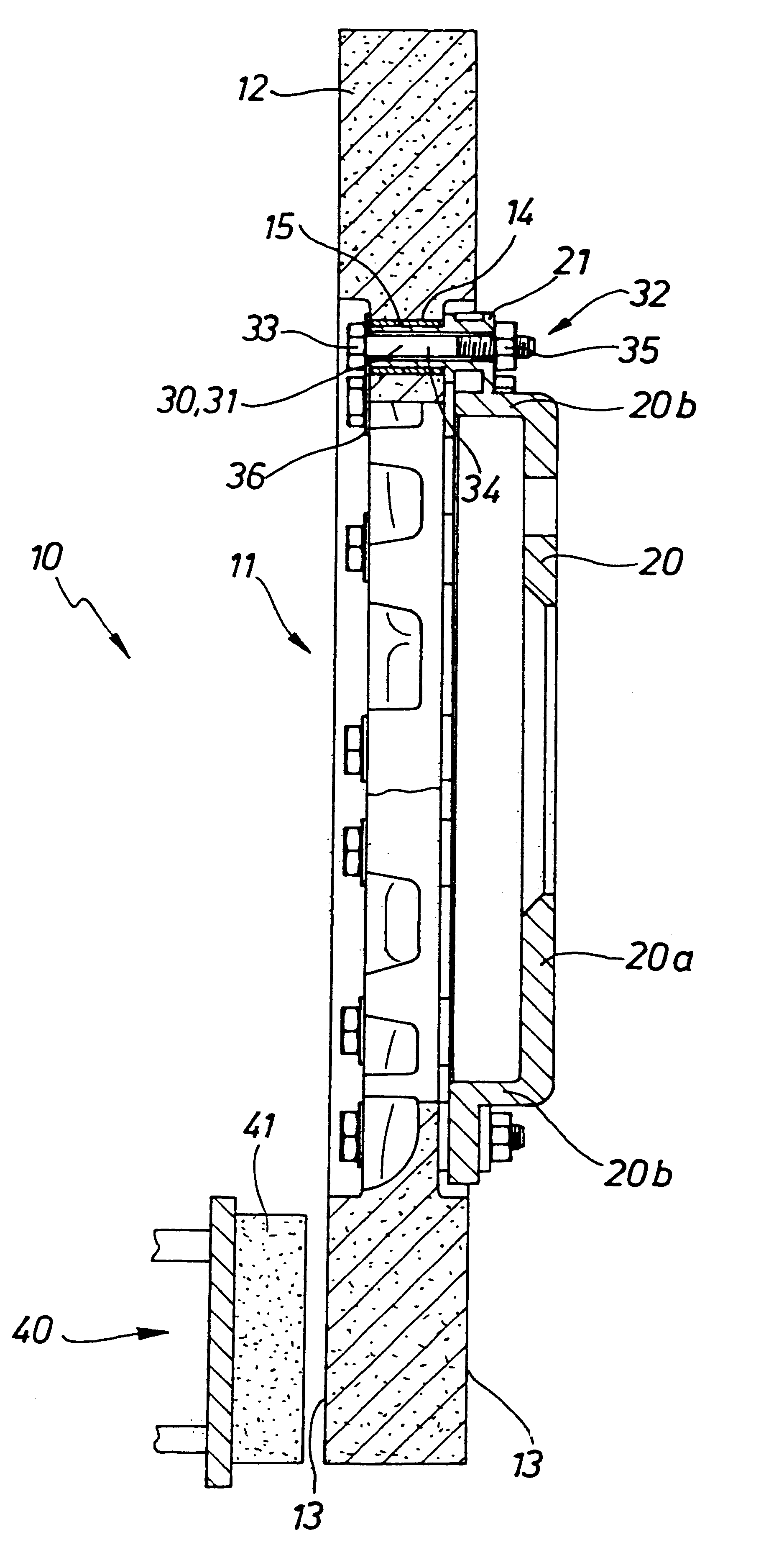
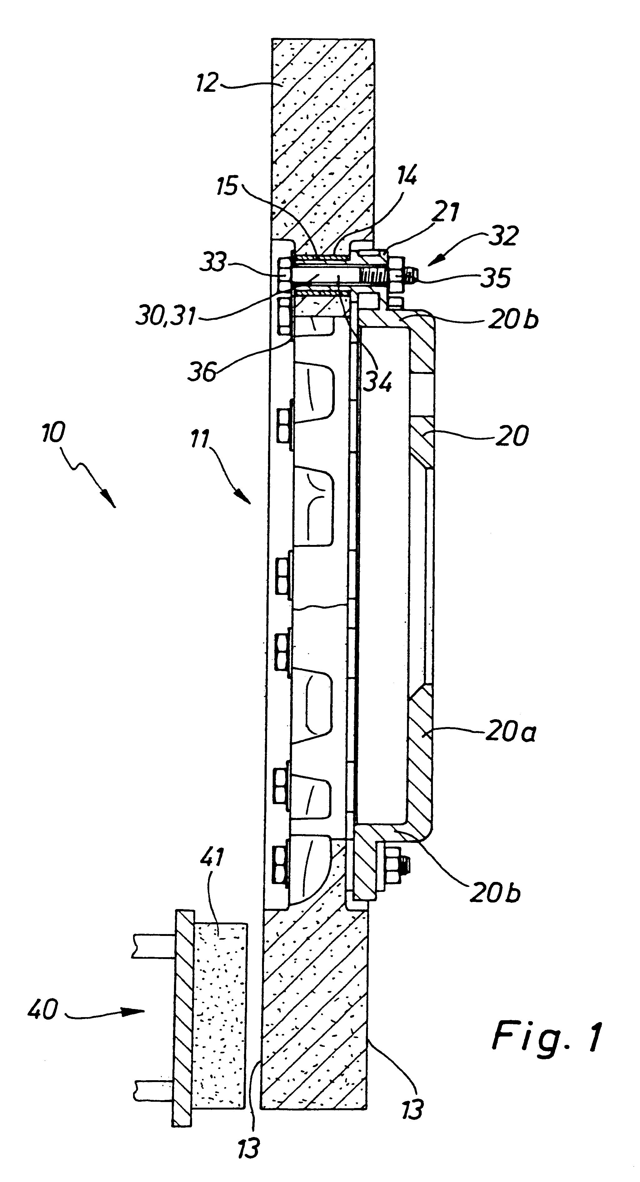
The drawing shows one embodiment of a brake unit 10 according to the present invention, made up of a disk brake 11 and brake pads 40 having friction linings 41. Disk brake 11 has a brake ring or brake rotor 12. The outer surfaces of brake rotor 12 serve as friction surfaces 13 for friction linings 40 of brake pads 41. At least friction surface 13, but preferably the entire brake unit 10, is made of a ceramic-metal composite material, in the exemplary embodiment having a composition with approximately 10 to 55 wt % silicon carbide, approximately 30 to 78 wt % carbon fibers or silicon carbide fibers that are preferably isotropically oriented short fibers, and approximately 0 to 25 wt % silicon. The hardness is in the range of, for example, from approximately 1600 to 2500 HV, per DIN 50133, and surface roughness Rx is approximately 2 to 15 .mu.m.

Mounted on disk brake 11 is an adapter or disk brake cup 20, preferably attached in the "floating" fashion shown in the Figure. Disk brake cup...


PUM


Abstract

A brake unit comprising at least one brake and at least one brake pad having at least one friction lining is described. The brake has a disk brake with a brake rotor made of a ceramic-metal composite (CMC) whose outer surface or surfaces at least partially form a friction surface for the at least one friction lining, and a disk brake cup that is mounted on the disk brake by way of one or more mounting elements. The friction surface of the disk brake has a hardness of approximately 1600 to 2500 HV, and the at least one friction lining has a coefficient of friction of approximately 0.3 to 0.5. The disk brake cup and/or the mounting elements form a corrosion-inhibiting attachment to the disk brake. The brake unit can be operated in corrosion-free fashion over a service life of at least approximately eight to 10 years or approximately 200,000 to 300,000 km.

Description

The present invention relates to a brake unit comprising at least one disk brake and at least one brake pad having at least one friction lining. More specifically, the brake unit includes a brake rotor made of a ceramic-metal composite (CMC) whose outer surface or surfaces at least partially form a friction surface for the at least one friction lining, and a disk brake cup that is mounted on the disk brake by way of one or more mounting elements.SUMMARY OF RELATED ARTIn high-performance brake units used both for motor vehicles and for rail vehicles, outstanding braking properties, excellent braking smoothness, and at the same time the longest possible service life are required. Conventional brake units having cast-iron disk brakes, however, have comparatively unfavorable wear rates in braking operation. In high-performance brake units, in addition to brake related wear, so-called "stroking wear," is particularly significant. This type of wear creates geometrical defects on the brake...

Claims


Application Information

Patent Timeline
Patent Type & Authority Patents(United States)
IPC IPC(8): F16D65/12F16D65/00F16D65/78
CPCF16D65/0006F16D65/12F16D2065/1316F16D2065/1368F16D2065/1392F16D2065/784F16D2200/0017F16D2200/0039F16D2200/006
Inventor NAUMANN, EMILREBSTOCK, KOLJARIEDEL, HANS-GEORGROSS, KARL-HEINZWOLFSRIED, STEPHAN
Owner FRENI BREMBO SPA
Why Eureka
Try Eureka