Torque transmission unit

Inactive Publication Date: 2001-10-16
ZF FRIEDRICHSHAFEN AG
View PDF11 Cites 30 Cited by
  • Summary
  • Abstract
  • Description
  • Claims
  • Application Information

AI Technical Summary

Benefits of technology

is to provide a torque transmission unit for a motor vehicle having good torsion damping characteristics while optimizing

Problems solved by technology

While the known means for torsion damping do reduce torsional vibrations, these known means are not sufficient particularly, for example, in luxury vehicles in which special vibration damping is expected and in compact economy vehicles which are designed for a particularly low energy consumption and therefore typically have a more pronounced vibration behavior within the drive train.
Although it is possible to employ an electric machine for additional torsion damping, the use of the electric machine for thi

Method used


Image

  • Torque transmission unit
  • Torque transmission unit
  • Torque transmission unit

Examples


Embodiment Construction

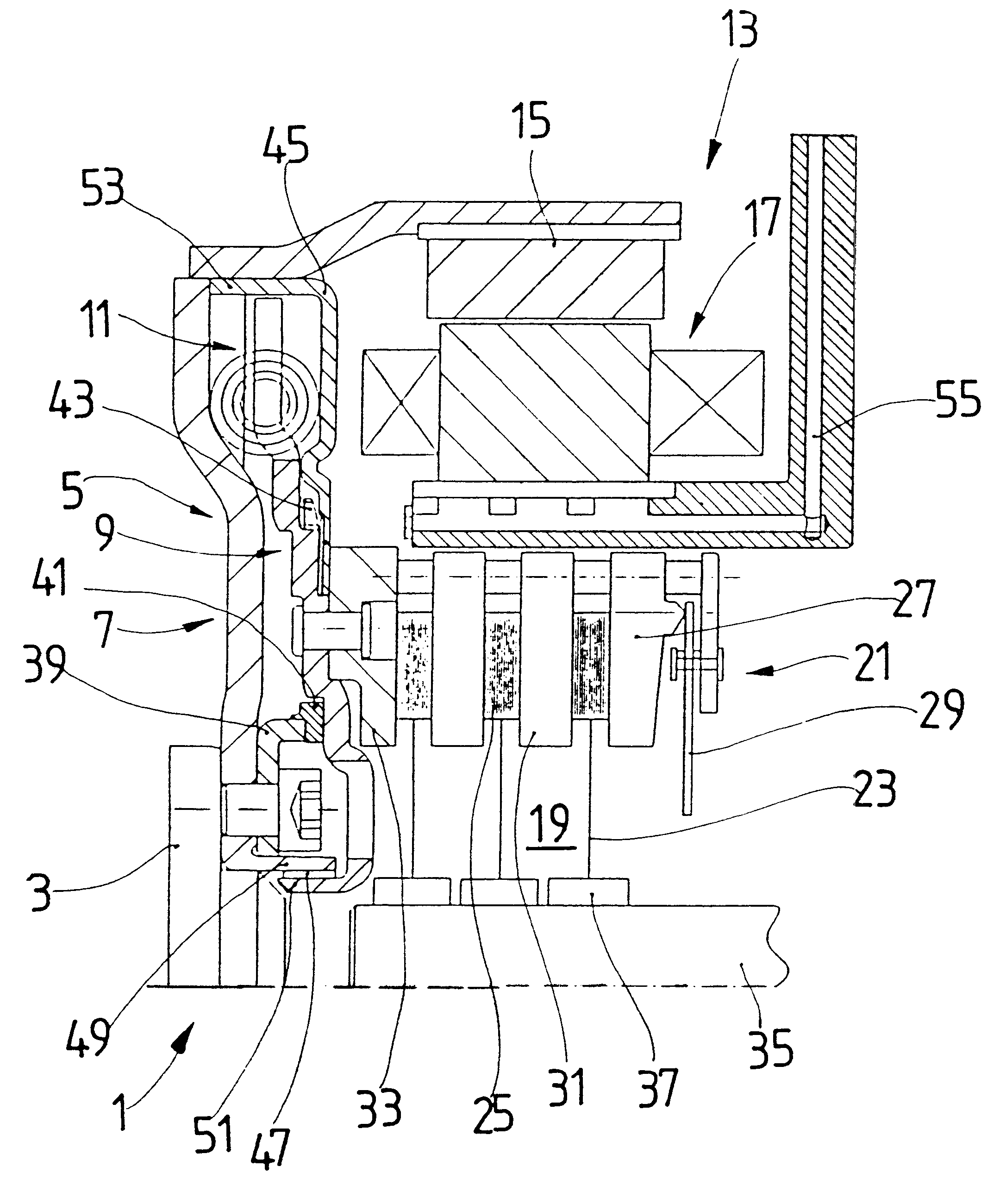
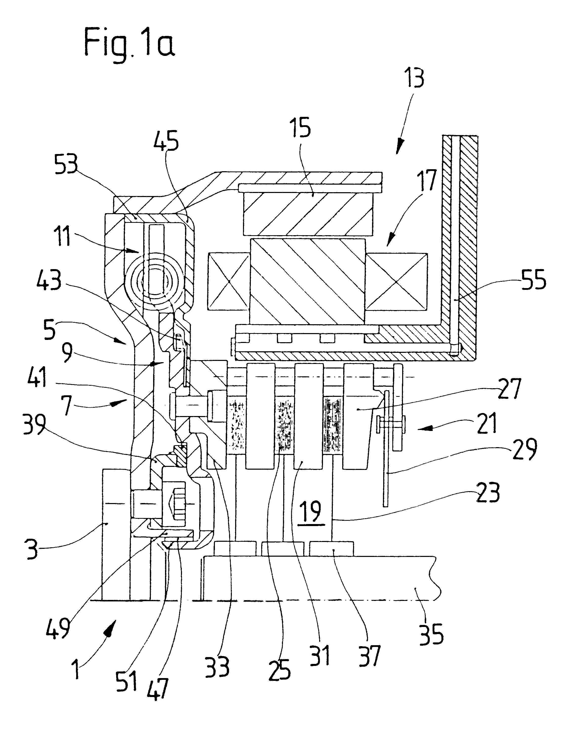
FIG. 1a shows a torque transmission unit 1 according to an embodiment of the present invention having an input shaft 3 operatively connected to an engine (not illustrated), i.e., an internal combustion engine, in a motor vehicle. A torsion damping device 5 having a primary mass 7 and a secondary mass 9 is connected to the input shaft 3. Circumferentially disposed spring devices 11 are arranged between the primary mass 7 and the secondary mass 9 for bracing the primary mass 7 relative to the secondary mass 9. Accordingly, the primary mass 7 is rotatable relative to the secondary mass 9 against an elastic force of the circumferentially disposed spring devices 11. This design of a torsion damping device is known, for example, from DE 36 30 398 C2 or DE 44 44 196 A1.

The torsion damping device 5 is followed in the axial direction by an electric machine 13, the essential components of which include a rotor 15 and a stator 17 arranged concentrically to one another. The electric machine 13 ...


PUM


Abstract

Torque transmission unit includes an input shaft and an output shaft with a torsion damping device functionally arranged between the input shaft and an output shaft. A shift clutch is also operatively arranged between the input shaft and the output shaft for selectively varying the torque transmitted from the input shaft to the output shaft. The torsion damping device has at least a primary mass and a secondary mass, the primary mass being effectively connected to the input shaft and the secondary mass being effectively connected to the output shaft. The torque transmission unit further comprises an electric machine with a stator and a rotor effectively connected to the input shaft. At least one of the shift clutch and the torsion damping device is arranged within an annular space delimited by the rotor and the stator of the electric machine.

Description

1. Field of the InventionThe invention relates to a torque transmission unit having a torsion damping device and a shift clutch arranged between an input shaft and an output shaft and an electric machine with a rotor concentrically arranged relative to a stator, the rotor being effectively connected with the input shaft.2. Description of the Related ArtA torque transmission unit is disclosed in German references DE 43 23 601 A1 and DE 43 23 602 A1 having an electric machine combined with a torsion damping device and a shift clutch. These references show that one of the shift clutch and the torsion damping device may be arranged within a central construction space delimited by the stator of the electric machine. Torsion damping elements of the torsion damping devices are shown as being integrated into the clutch disk of the shift clutch. While the known means for torsion damping do reduce torsional vibrations, these known means are not sufficient particularly, for example, in luxury ...

Claims


Application Information

Patent Timeline
IPC IPC(8): F02N11/04F16F15/18F16F15/10F16F15/134F16F15/131
CPCF02N11/04F16F15/18F16F15/1343Y10T74/134
Inventor LINK, ACHIMREISSER, WOLFGANGVOGT, SEBASTIAN
Owner ZF FRIEDRICHSHAFEN AG
Why Eureka
Try Eureka